
Steel and plastic composite bionic blade

A steel-plastic composite and blade technology, applied in the field of composite bionic blades, can solve problems such as the influence of generator working efficiency, slow blade rotation, weak impact force, etc., to achieve full and effective utilization of hydraulic resources, stable frequency, and increased rotational speed. The effect of stability

Inactive Publication Date: 2012-07-11
CHONGQING TONGLI INDAL
View PDF6 Cites 7 Cited by
  • Summary
  • Abstract
  • Description
  • Claims
  • Application Information

AI Technical Summary

Problems solved by technology

[0003] The blades of traditional hydroelectric generators are rigid, so that the rotation of the blades is determined by the flow velocity of the water flow. The impact force generated by the rapid water flow is strong, and the blades rotate quickly. The impact force generated by the slow water flow is weak, and the blades rotate slowly. The working efficiency of the generator will be affected, and a complex turning device must be set for adjustment

Method used


Image

  • Steel and plastic composite bionic blade
  • Steel and plastic composite bionic blade
  • Steel and plastic composite bionic blade

Examples


Embodiment Construction

[0018] The preferred embodiments of the present invention will be described in detail below in conjunction with the accompanying drawings; it should be understood that the preferred embodiments are only for illustrating the present invention, rather than limiting the protection scope of the present invention.

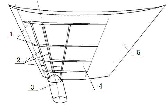
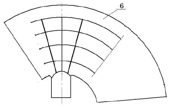
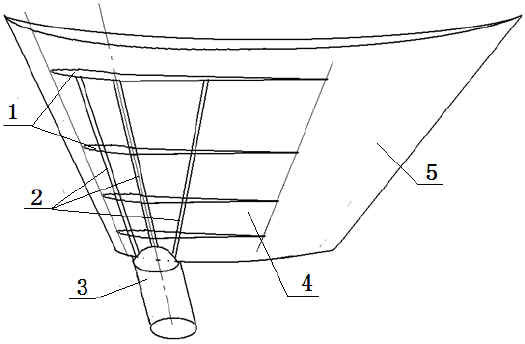
[0019] figure 1 Schematic diagram of the structure of the steel-plastic composite bionic blade provided by the embodiment of the present invention, figure 2 The steel-plastic composite bionic blade provided for the embodiment of the present invention is a schematic diagram of unfolding, and the steel-plastic elastic blade is expanded schematically 6, as shown in the figure: the steel-plastic composite bionic blade provided by the present invention includes blade 4, shaft 3 (or steel Seat) and the blade elastic area 5, the blade is a reinforced elastic blade 4 coated with plastic, the thickness of the blade changes from the middle to the edge in a streamlined shape, and...


PUM


Abstract

The invention discloses a steel and plastic composite bionic blade, which comprises a blade body, a rotary shaft and a blade holder. The thickness of the blade body is reduced from the middle to the edge in a streamline manner, the blade body is in the shape of an annular sector, the cross section of the blade body is arched, the rotary shaft is arranged on the short-arc side of the annular sector and deviates from the center line of the surface of the blade body, namely the rotary shaft is arranged at the front end of the rotation direction of the blade. The blade body is provided with a plurality of longitudinal reinforced ribs and a plurality of transverse reinforced ribs, and a blade elastic area is arranged at the back end of the blade body. The integral blade is in the shape of an annular sector which is smooth and streamlined and covered with plastics. The steel and plastic composite bionic blade utilizing reinforced bars as ribs is formed by plastics and a web body. Due to the fact that the stress of the blade elastic area is different along with change of impact force of water flow to a water turbine, the angle of the blade is changed automatically, instability caused by change of the impact force is compensated and stability of rotation speed of the water turbine is improved under elasticity and flexibility action of the blade, and accordingly stability in voltage and frequency of a water turbine power generator is guaranteed and the adaptable flow range of the water turbine power generator is wider while efficiency thereof is higher.

Description

technical field [0001] The invention relates to a blade structure of a hydraulic generator, in particular to a composite bionic blade of a hydraulic generator. Background technique [0002] Among the technologies using new energy, hydropower technology has received extensive attention. Its principle is to generate electricity through flowing water acting on water wheels, generally including water turbine generators, pumps, high-level water towers, filling nozzles and electric energy. Management and other components, the structure is relatively complicated, and the cost is very high. The construction of hydropower stations must also be carried out according to specific geographical conditions. Hydropower generation must build dams and have water flow drops. Therefore, the construction of hydropower stations is very restricted. However, my country and the world are rich in hydropower resources. Especially in some cities, roads, bridges, enterprises and residents built by rivers ...

Claims


Application Information

Patent Timeline
IPC IPC(8): F03B3/12
CPCY02E10/223Y02E10/20
Inventor 沈家同沈利川
Owner CHONGQING TONGLI INDAL
Learn More