Lifting rod connecting structure and lifting rod

A connection structure and lifting rod technology, which is applied in the connection of rods, connecting components, friction clamping detachable fasteners, etc., can solve the problems of large size, unsuitable for simple applications, high cost of automatic lifting devices, etc., to achieve Simple connection structure design, continuous height adjustment, and low processing and manufacturing costs

Inactive Publication Date: 2012-07-11
OCEANS KING LIGHTING SCI&TECH CO LTD +1
View PDF7 Cites 12 Cited by
  • Summary
  • Abstract
  • Description
  • Claims
  • Application Information

AI Technical Summary

Problems solved by technology

However, the cost of the automatic lifting device is too high, and the volume is large, which is not suitable for simple applications

Method used


Image

  • Lifting rod connecting structure and lifting rod
  • Lifting rod connecting structure and lifting rod
  • Lifting rod connecting structure and lifting rod

Examples


Embodiment Construction

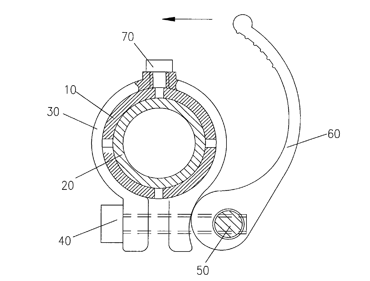
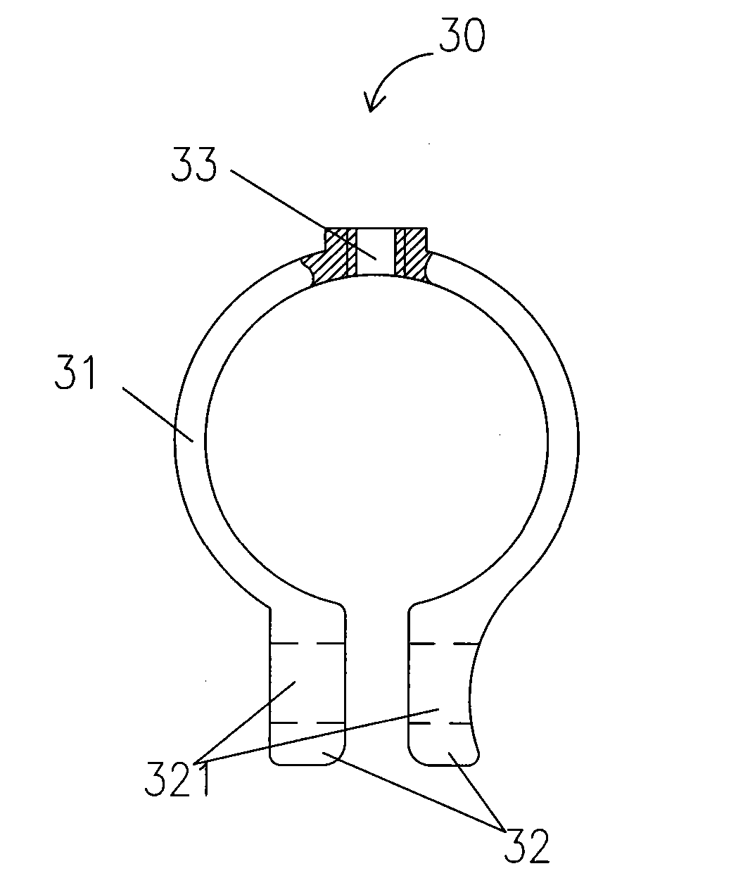
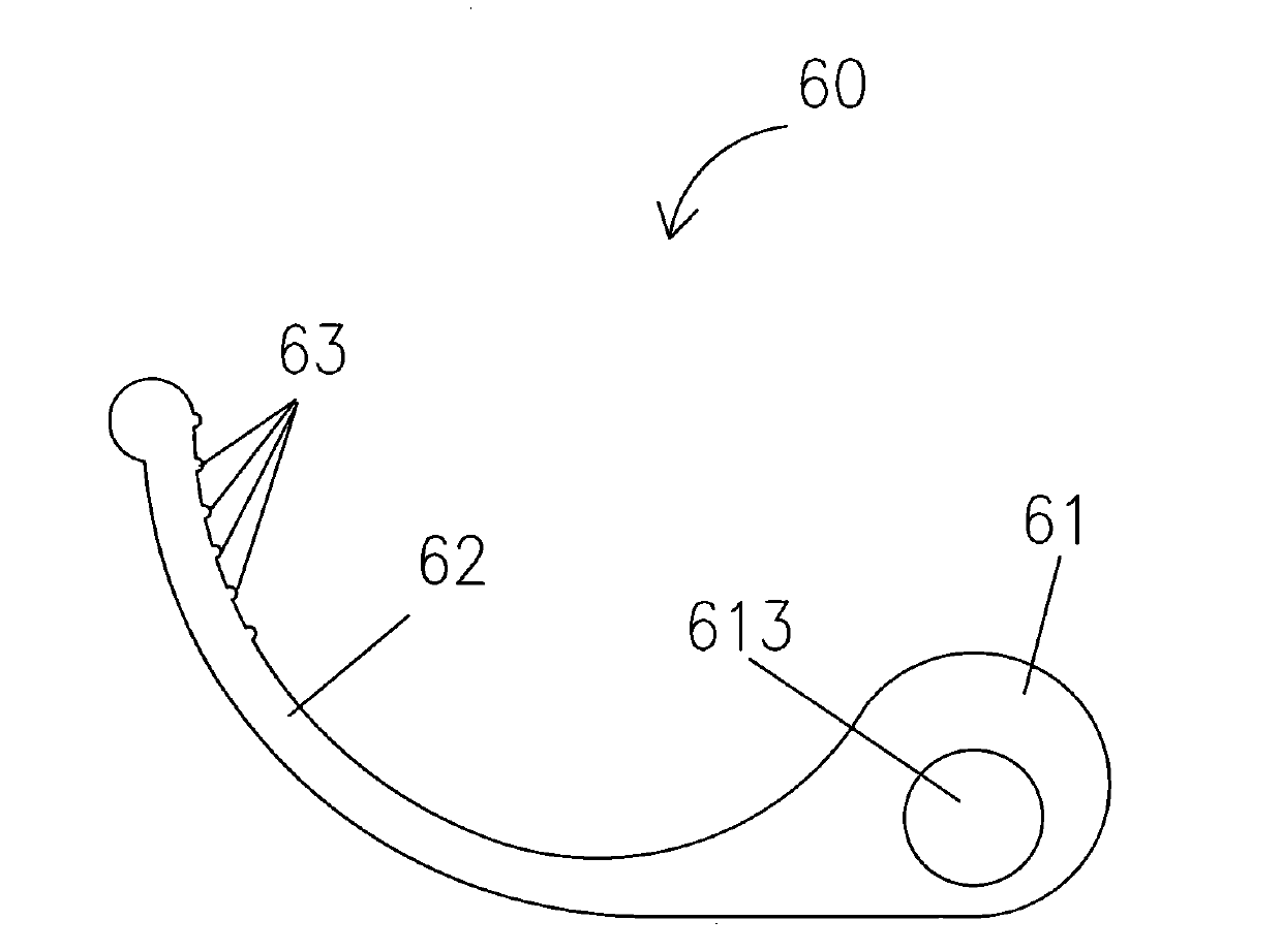
[0032] The lifting rod connection structure of the preferred embodiment of the present invention is as follows: figure 1 shown, see also figure 2 and image 3 , used to connect the outer tube 10 and the inner tube 20 coaxially socketed on the locking lifting rod to prevent the relative movement of the outer tube 10 and the inner tube 20 , including a lock hoop for applying pressure to the outer tube 10 to hold the inner tube 20 tightly 30. Wherein, the lock hoop 30 is an annular structure with an opening, the two opening ends of the lock hoop 30 are correspondingly provided with fixing holes 321, and locking screws 40 are perforated in the two opposite fixing holes 321, and the tail ends of the locking screws 40 are connected to In the screw hole (not shown) of a rotating shaft 50, the opening end of the locking collar 30 is locked to initially realize the locking and positioning of the outer tube 10 and the inner tube 20, but at this time, the inner tube 20 can still be lo...


PUM


Abstract

The invention relates to a lifting rod connecting structure and a lifting rod, wherein the lifting rod connecting structure comprises a lock hoop which is used for applying pressure an outer pipe so as to hold an inner pipe tightly, and the lock hoop is of a ring-shaped structure with openings; two opening ends of the lock hoop are correspondingly provided with fixed holes; locking screws are arranged in the fixed holes in a penetrating manner; the tail ends of the locking screws are connected in screw holes of a rotating shaft so as to lock the opening ends of the lock hoop tightly; a hand fastener is relatively rotatably connected to the rotating shaft, and the outer edge of one end, which is connected with the rotating shaft, of the hand fastener is set as a continuous curved surface tangential to the outer surfaces of the opening ends of the lock hoop; the distances from points on the continuous curved surface to the center of the rotating shaft are unequal so as to apply pressure with different sizes on the opening ends of the lock hoop and adjust the size of the pressure applied by the lock hoop on an outer pipe. The lifting rod connecting structure has the advantages that the design is simple, the processing and manufacturing cost is low, the installation and the use are convenient, and the continuous adjustment of the height can be realized.

Description

technical field [0001] The invention relates to a height adjustment mechanism, more specifically, to a connection structure of a lifting rod and a lifting rod. Background technique [0002] At present, a lifting mechanism is used in many occasions. The lifting mechanism with a relatively simple structure generally adopts an inner tube coaxially socketed in an outer tube, and the inner tube is stretched to a predetermined position relative to the outer tube and then connected and tightened. Generally, screws can be used to connect the inner pipe and the outer pipe. Although this connection method is simple, the connection is not reliable, and the processing and manufacturing costs are relatively high, and the operation is also relatively troublesome. [0003] In addition, gaps of different heights are arranged on the outer tube, positioning blocks are set on the inner tube, and the adjustment of different heights is realized by hooking the positioning blocks in the gaps. The...

Claims


Application Information

Patent Timeline
Patent Type & Authority Applications(China)
IPC IPC(8): F16B7/14F16B7/04F16B2/18
Inventor 周明杰何龙
Owner OCEANS KING LIGHTING SCI&TECH CO LTD
Why Eureka
Try Eureka