Winding device

A winding device and wire trough technology, which is used in transportation and packaging, transportation of filamentous materials, and thin material processing, etc., can solve the problems of uncompact winding, prone to gaps and overlaps in winding, and uneven wire ends. , to achieve the effect of compact winding

Active Publication Date: 2014-02-19
WUHAN KATTOR IND
View PDF6 Cites 1 Cited by
  • Summary
  • Abstract
  • Description
  • Claims
  • Application Information

AI Technical Summary

Problems solved by technology

[0002] The winding device is used to wind multiple sets of wires. Due to the thickness of the wires, the wires cannot completely coincide with the cross-section of the rotating shaft during the winding process, and the winding will not be compact during the winding process. prone to gaps and overlaps
At the same time, the angle and strength of the winding are not uniform, and the thread ends are uneven

Method used


Image

  • Winding device

Examples


Embodiment Construction

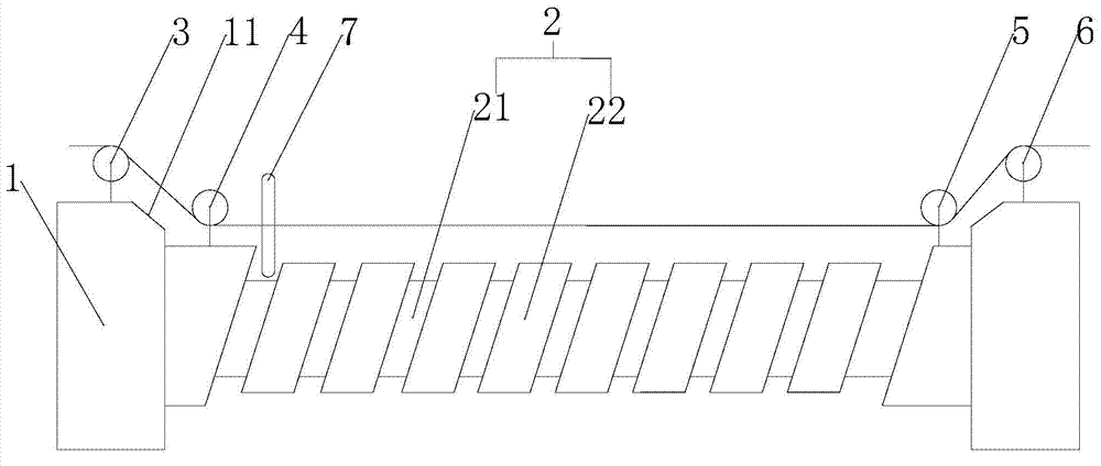
[0009] Such as figure 1 as shown, figure 1 It is a structural schematic diagram of a winding device proposed by the present invention.

[0010] refer to figure 1 , a winding device proposed by the present invention, including a rotating shaft 2, the two ends of the rotating shaft 2 are mounting seats 1, a number of wire grooves 21 are arranged on the rotating shaft 2, the two sides of the wire groove 21 are ridges 22, and the sides of the wire groove 21 The edge and the center line of the rotating shaft 2 are in a non-perpendicular relationship, and the two ends of the rotating shaft 2 are provided with end plates near the mounting seat 1, and the mounting seat 1 and the end plates at both ends of the rotating shaft 2 are sequentially provided with a first pulley 3 and a second pulley 4 , the third pulley 5, the fourth pulley 6, the traction line enters from the first pulley 3 and walks around the second pulley 4, the third pulley 5 is pulled out from the fourth pulley 6, an...


PUM


Abstract

The invention discloses a winding device which comprises a rotating shaft. The two ends of the rotating shaft are provided with mounting bases. The rotating shaft is provided with a plurality of wire grooves, the two sides of each wire groove are ridge-shaped portions, and the side edges of the wire grooves are not perpendicular to the center line of the rotating shaft; the two ends, close to the mounting bases, of the rotating shaft are provided with end plates; the mounting bases at the two ends of the rotating shaft and the end plates are sequentially provided with a first pulley, a second pulley, a third pulley and a fourth pulley; a pull wire is fed from the first pulley, wound around the second pulley and the third pulley and drawn out from the fourth pulley, the drawn-out end of the pull wire is connected with a take-up device which drives the drawn-out end of the pull wire to move, the fed end of the pull wire is connected with an unwinding device used for discharging a wire, the part, located between the second pulley and the third pulley, of the pull wire is rotatably connected with a first load, the two end of the first load is provided with a flat and smooth curved surface, and the upper portions, close to one side of the rotating shaft, of the mounting bases are provided with slopes. The improvement to the winding device is achieved, and the winding device is simple in structure and can allow the wire to be wound to be compact and flat.

Description

technical field [0001] The invention relates to a winding device. Background technique [0002] The winding device is used to wind multiple sets of wires. Due to the thickness of the wires, the wires cannot completely coincide with the cross-section of the rotating shaft during the winding process, and the winding will not be compact during the winding process. There are gaps and overlaps between them. At the same time, the angle and strength of the winding are not uniform, and the thread ends are uneven. Contents of the invention [0003] In order to solve the technical problems existing in the background technology, the present invention proposes a winding device, which improves the winding device. The structure is simple, and the winding can be compact and smooth. [0004] A winding device proposed by the present invention includes a rotating shaft, the two ends of the rotating shaft are mounting seats, a number of wire grooves are arranged on the rotating shaft, the ...

Claims


Application Information

Patent Timeline
Patent Type & Authority Applications(China)
IPC IPC(8): B65H54/48B65H54/52
Inventor 陈敏兆赵理郁
Owner WUHAN KATTOR IND
Why Eureka
Try Eureka