Convenient-to-clean sputum suction device for pneumology department

A technology of respiratory department and sputum suction tube, which is applied in the field of sputum suction device for respiratory department that is easy to clean. It can solve the problems of increased difficulty in cleaning, inability to quickly clean and dry sputum suction on site, and achieve the goal of improving impact Effect

Inactive Publication Date: 2020-12-04
李瑞
View PDF1 Cites 4 Cited by
  • Summary
  • Abstract
  • Description
  • Claims
  • Application Information

AI Technical Summary

Problems solved by technology

[0005] The purpose of the present invention is to solve the problem in the prior art that after the sputum suction is completed, the structure of the replaceable sputum storage tank needs to be removed and then sent to the flushing site for flushing. During the process of sending to the flushing site, the internal sputum storage is prone to occur. Due to dryness, it is more difficult to clean, and it is impossible to clean quickly at the sputum suction site. Therefore, an easy-to-clean respiratory sputum suction device is proposed.

Method used


Image

  • Convenient-to-clean sputum suction device for pneumology department
  • Convenient-to-clean sputum suction device for pneumology department
  • Convenient-to-clean sputum suction device for pneumology department

Examples


Embodiment Construction

[0033] The technical solution of this patent will be further described in detail below in conjunction with specific embodiments.

[0034] Embodiments of the present patent are described in detail below, examples of which are shown in the drawings, wherein the same or similar reference numerals designate the same or similar elements or elements having the same or similar functions throughout. The embodiments described below by referring to the figures are exemplary and are only used for explaining the patent, and should not be construed as limiting the patent.

[0035] In the description of this patent, it is to be understood that the terms "center", "upper", "lower", "front", "rear", "left", "right", "vertical", "horizontal", The orientation or positional relationship indicated by "top", "bottom", "inner", "outer", etc. is based on the orientation or positional relationship shown in the drawings, and is only for the convenience of describing this patent and simplifying the des...


PUM


Abstract

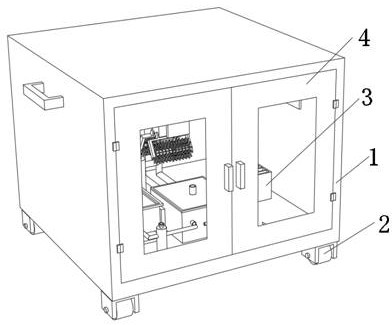
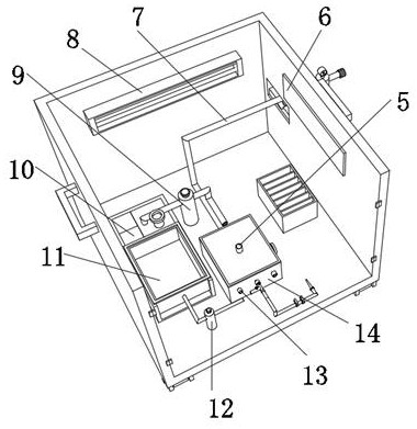
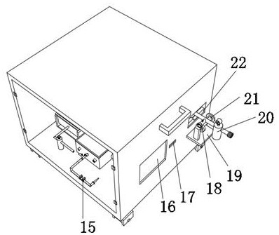
The invention discloses a convenient-to-clean sputum suction device for a pneumology department, and relates to the technical field of sputum suction devices for the pneumology department, and aims tofully clean sputum adhered to a sputum suction collection box. The sputum suction device specifically comprises a box body, two cover plates are connected to the outer wall of one side of the box body through hinges, the sputum aspiration collection box is arranged on the outer wall of the top of the box body, a graduated scale is arranged on the inner wall of one side of the sputum aspiration collection box, three connectors are fixed to the outer wall of one side of the sputum aspiration collection box through bolts, a liquid outlet pipe is fixed to the outer wall of one side of the sputumsuction collection box through screws, a sealing cover plate is slidably connected to the outer wall of the top of the sputum suction collection box, a water disc is welded to the outer wall of the bottom of the sealing cover plate, and two or more flushing heads are fixed to the outer wall of the bottom of the water disc through bolts. Water in the water tank can be pressurized through a pressurepump, meanwhile, an insertion hole is formed in the outer wall of the top of the sealing cover plate, and the water in the water tank can be rapidly guided into the water disc through a flushing pipe.

Description

technical field [0001] The invention relates to the technical field of a sputum suction device for respiratory department, in particular to a sputum suction device for respiratory department which is easy to clean. Background technique [0002] Some patients in the Department of Respiratory Medicine have too much sputum. If the sputum is not sucked out in time, the patient will have dyspnea, which threatens the patient's life. The manual sputum suction device is insufficient in power, making it difficult to suck sputum. There will be a phenomenon that the inner wall of the respiratory tract will be injured by the rubber tube, and the damage to the inner wall of the respiratory tract will cause inflammation, making it more difficult for the patient to breathe and the sputum to be excreted more difficult. Sometimes the sputum is too viscous to be sucked out. It is necessary to pull out the suction tube and inject normal saline or sodium bicarbonate solution into the patient's ...

Claims


Application Information

Patent Timeline
Patent Type & Authority Applications(China)
IPC IPC(8): A61M1/00A61M11/00A61M31/00B08B9/087B08B9/093B65H75/38B65H75/44A61L2/10A61L2/04
CPCA61L2/04A61L2/10A61M1/0023A61M11/00A61M31/00A61M2210/1039B08B9/087B08B9/093B65H75/38B65H75/44A61M2210/005
Inventor 李瑞马武豪
Owner 李瑞
Why Eureka
Try Eureka