Discharge mechanism of 3D printer

A 3D printer and discharge mechanism technology, applied in the field of 3D printing, can solve problems such as affecting the machining accuracy of the workpiece, the linear printing consumables being stuck, and affecting the normal wire output of the nozzle, so as to achieve a small size, reduce the risk of wire breakage, and reduce the number of nozzles. The effect of leaking wires

Active Publication Date: 2014-05-14
J H TECH ELECTRONICS GZ LTD
View PDF2 Cites 3 Cited by
  • Summary
  • Abstract
  • Description
  • Claims
  • Application Information

AI Technical Summary

Problems solved by technology

At present, the output mechanism of the 3D printer is usually as follows: figure 1 As shown, it includes a motor 11, a gear 12 driven by the motor, and a press wheel 13 located on the side of the gear 12. The gap formed between the press wheel 13 and the gear 12 is just enough for the linear printing consumables 14 to pass through. The motor 11 and the gear 12 squeeze the linear printing consumables 14 to extrude the linear printing consumables 14. During the use of this discharge mechanism, because the gap between the gear 12 and the pressing wheel 13 is fixed, it cannot be applied to The conveying of linear printing consumables with different diameters, and the linear printing consumables often appear to be stuck, which affects the normal filament discharge of the nozzle
[0006] In order to overcome the defects that the above-mentioned discharge mechanism exists, some discharge mechanisms are also in the above-mentioned figure 1 On the basis of the shown structure, the pressing wheel 13 is set as a movable part, and then a spring is used to exert pressure on the pressing wheel 13 towards the gear 12, so that the spring can be used to automatically adjust the pressing wheel 13 and the gear 12 The gap between them is suitable for the conveyance of linear printing consumables of different diameters. However, no matter what printing speed is, the pressure of the pressing wheel 13 and the gear 12 on the linear printing consumables 14 (that is, the pressing force) is always consistent. , cannot provide enough pressure during high-speed printing, resulting in slippage phenomenon, which seriously affects the machining accuracy of the workpiece

Method used


Image

  • Discharge mechanism of 3D printer
  • Discharge mechanism of 3D printer
  • Discharge mechanism of 3D printer

Examples


Embodiment Construction

[0030] Below, in conjunction with accompanying drawing and specific embodiment, the present invention is described further:

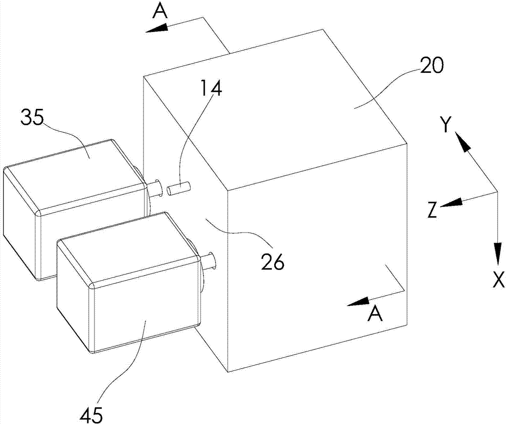
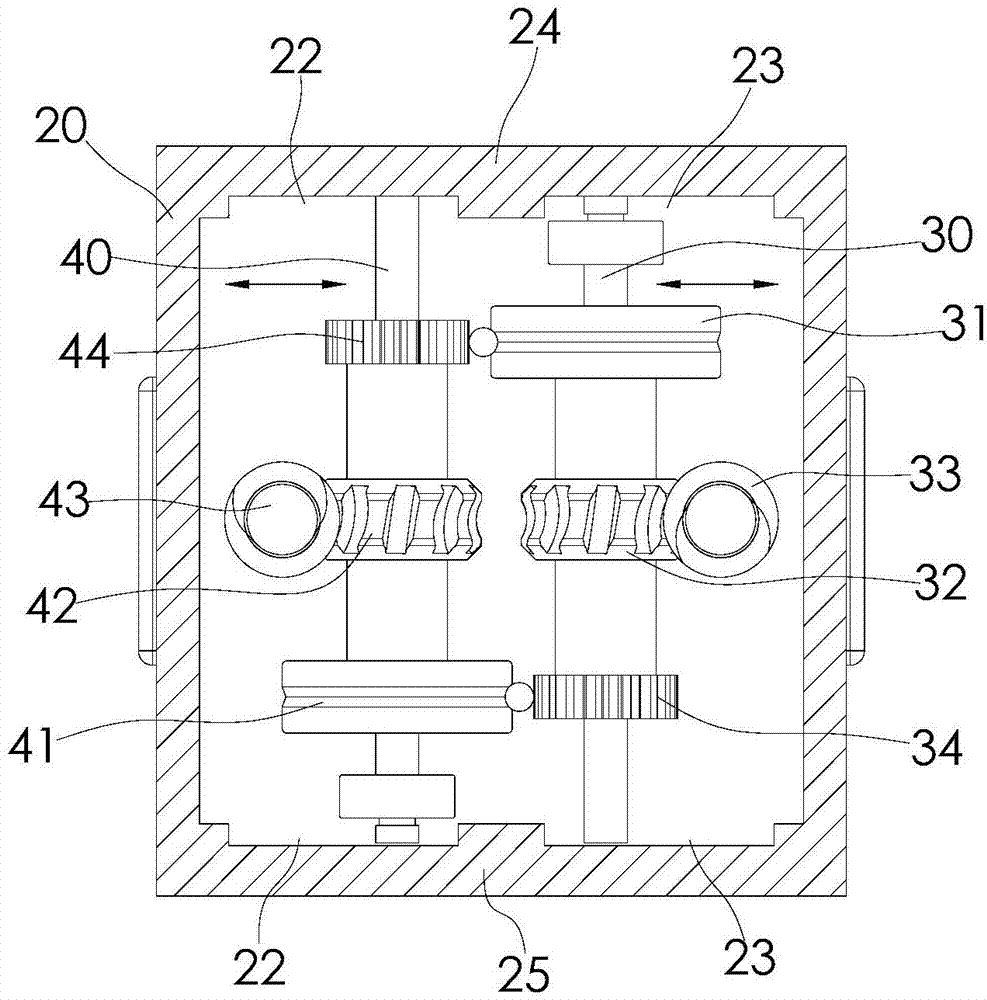
[0031] like figure 2 , 3 , 4, is a discharge mechanism of a 3D printer of the present invention, which includes a box 20, a first rotating shaft 30, a second rotating shaft 40, the box 20 includes a front support plate 24 and a rear support plate 25, the front support The both sides of plate 24 are respectively provided with first chute 23 and second chute 22, same, the both sides of rear support plate 25 are respectively provided with first chute 23 and second chute 22, two first chutes 23 is facing forward and backward and extending along the width direction of the box body 20 (that is, the Y direction in the figure), two second chute 22 are facing front and rear and extending along the width direction of the box body 20, the first rotating shaft 30 and the second rotating shaft 40 is located inside the box body 20 and extends along the length dire...


PUM


Abstract

The invention provides a discharge mechanism of a 3D printer. The discharge mechanism comprises a box, a first rotating shaft, a second rotating shaft and a first drive motor, wherein the box at least comprises a front support plate and a rear support plate; the first rotating shaft can slide along the width direction of the box; a first material pressing wheel and a first worm wheel are synchronously connected to the first rotating shaft; a second material pressing wheel is synchronously connected to the second rotating shaft; a gap for linear printing supplies to pass through is formed between the circumferential surfaces of the second and first material pressing wheels; a body part of the first drive motor is fixed on the box; a first worm meshed with the first worm wheel is synchronously connected to a rotating shaft of the first drive motor. The discharge mechanism achieves self-balancing of wire pressing forces by adopting a worm wheel and worm mechanism, thus reducing the risk of fracture of wires of the linear printing supplies. Meanwhile, the discharge mechanism can reduce the slipping possibility of the linear printing supplies, thus improving the reliability of the 3D printer.

Description

[0001] technical field [0002] The invention relates to the technical field of 3D printing, in particular to a printing consumable discharge mechanism of a 3D printer. [0003] Background technique [0004] 3D printing technology is a rapid prototyping technology for workpieces. It is based on the digital model file of the workpiece, using materials with viscous properties after heating and softening, such as metal or plastic, to form the workpiece by layer-by-layer printing. [0005] When the 3D printer is working, it usually uses the extruder to convey the linear printing consumables to the inside of the nozzle, so that the printing consumables can be quickly heated to the softening temperature inside the nozzle. At present, the output mechanism of the 3D printer is usually as follows: figure 1 As shown, it includes a motor 11, a gear 12 driven by the motor, and a press wheel 13 located on the side of the gear 12. The gap formed between the press wheel 13 and the gear 1...

Claims


Application Information

Patent Timeline
Patent Type & Authority Applications(China)
IPC IPC(8): B29C67/00B22F3/105B22F3/115
Inventor 李一奇萧嘉鑫
Owner J H TECH ELECTRONICS GZ LTD
Why Eureka
Try Eureka