Tension controlling and speed measuring system of coating machine

A tension control and coating machine technology, applied in the field of coating machines, can solve the problems of high equipment cost and large space occupation, and achieve the effects of large contact area, improved accuracy and reduced cost

Inactive Publication Date: 2017-06-20
苏州威格半导体材料有限公司
View PDF7 Cites 4 Cited by
  • Summary
  • Abstract
  • Description
  • Claims
  • Application Information

AI Technical Summary

Problems solved by technology

[0004] But even if this kind of precision intelligent winding machine is used, the equipment cost is high and the space occupied is large

Method used


Image

  • Tension controlling and speed measuring system of coating machine
  • Tension controlling and speed measuring system of coating machine
  • Tension controlling and speed measuring system of coating machine

Examples


Embodiment Construction

[0034] Below in conjunction with specific embodiment, content of the present invention is described in further detail:

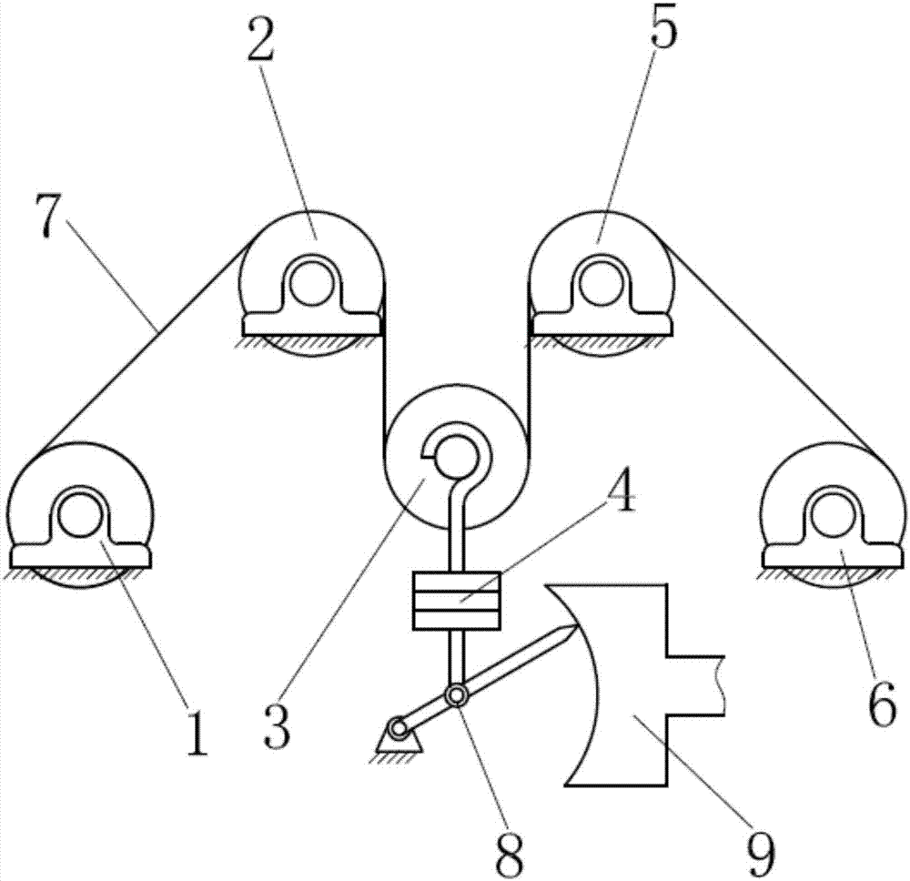
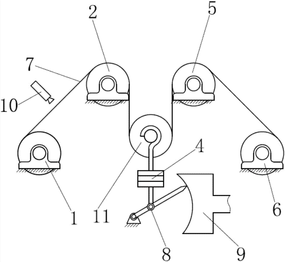
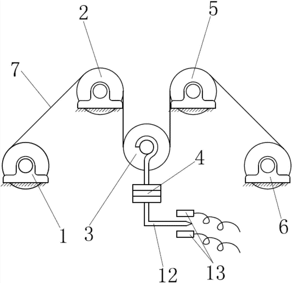
[0035] In order to achieve the purpose of the present invention, figure 1 is a schematic diagram of an embodiment of the present invention. The base material 7 bypasses the unwinding roller 6 , the second idler roller 5 , the speed measuring roller 3 , the first idler roller 2 and the winding roller 1 from the feeding direction to the discharging direction. Wherein, the winding roller 1, the first idle roller 2, the second idle roller 5, and the unwinding roller 6 are all fixed on the support, and the winding roller 1, the first idle roller 2, the second idle roller 5, and the unwinding roller 6 In contact with the lower surface of the substrate 7, the speed measuring roller 3 is in contact with the upper surface of the substrate 7, the speed measuring roller 3 provides a certain tension to the substrate 7 by its own weight for free suspension, and the spee...


PUM


Abstract

The invention discloses a coating machine tension control and speed measurement system. Including; winding roller, first idle roller, tension roller, second idle roller, unwinding roller, substrate, speed sensor, wherein; winding roller is driven by a servo motor, and the servo motor controls the speed of winding roller; tension roller Equipped with a tension sensor, the speed measuring roller floats freely and is in contact with the upper surface of the substrate, and uses its own weight to provide tension to the substrate; the substrate passes through the unwinding roller, the second idler roller, the tension roller, and the second roller respectively from the moving direction. An idler roller and a winding roller; the first idler roller, the second idler roller, the unwinding roller, and the winding roller are all fixed on the bracket; the unwinding roller contains a clutch; the clutch and the tension sensor form a closed-loop feedback circuit, and the servo The motor and speed sensor form a closed-loop feedback circuit. The invention has a compact structure, reduces the space occupied by equipment, provides a simple and reliable feedback mechanism, applies controllable tension to the base material and improves the accuracy of speed measurement.

Description

technical field [0001] The invention relates to a coating machine, in particular to a coating machine tension control and speed measurement system. Background technique [0002] The main structure of the coating machine is to wind the substrate on several guide rollers to form a certain film path, and the equipment generates a certain tension to tension the substrate to run. [0003] Chinese utility model patent specification CN203558648U discloses a precision intelligent winding machine. Including brackets, guide rails, pressing arm components, roller sets, tape feeding servo motors, reels and their pneumatic equipment, central controllers, reel pulleys and their motors, etc., the wrapped fabric is wound into the rollers in turn through the feed bracket. Each roller passes through the guide rollers on the pressing arm assembly, and then winds onto the reel through the guiding head; the pressing arm assembly is installed on the guide rail and driven by a synchronous belt; t...

Claims


Application Information

Patent Timeline
Patent Type & Authority Applications(China)
IPC IPC(8): B65H43/00B65H23/195B65H23/26
CPCB65H43/00B65H23/1955B65H23/26B65H2701/19
Inventor 张海銮欧阳俊波程园园冯宗宝章婷刘德昂曲亚东钱磊张德龙
Owner 苏州威格半导体材料有限公司
Why Eureka
Try Eureka