
Method for designing combined sealing device used in low speed and heavy load conditions of bearing

A low-speed heavy-duty, sealing device technology, applied in the direction of bearing components, shafts and bearings, mechanical equipment, etc., can solve the problems of insufficient skeleton rigidity of seals, reduce the use effect of seals, and reduce the use effect of seals, etc. Longevity, reduced maintenance, reduced wear and tear

Inactive Publication Date: 2012-07-11
LUOYANG BEARING SCI & TECH CO LTD
View PDF7 Cites 2 Cited by
  • Summary
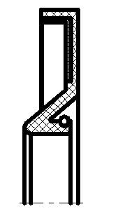
  • Abstract
  • Description
  • Claims
  • Application Information

AI Technical Summary

Problems solved by technology

[0008] 1. If the contact surface of the seal is too long, the friction force generated is relatively large, which will easily cause the contact surface to wear prematurely and reduce the use effect of the seal;
[0009] 2. The skeleton rigidity of the seal is not enough, it is easy to cause the deformation of the seal during the installation process, so that the actual use effect of the actual seal is reduced

Method used


Image

  • Method for designing combined sealing device used in low speed and heavy load conditions of bearing
  • Method for designing combined sealing device used in low speed and heavy load conditions of bearing
  • Method for designing combined sealing device used in low speed and heavy load conditions of bearing

Examples


Embodiment Construction

[0031] The present invention is a design method for a combined sealing device used in low-speed and heavy-load working conditions of bearings. The present invention can be explained in more detail through the following examples. The present invention is not limited to the following examples, and the purpose of the present invention is disclosed All changes and modifications within the scope of the invention are intended to be protected.

[0032] The specific numerical values ​​listed below are for reference only, and these specific numerical values ​​are not unique, but must comply with and satisfy the present invention.

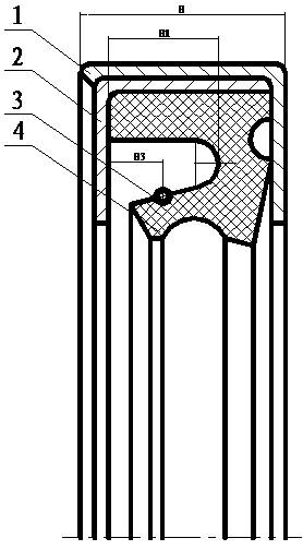
[0033] First, set the width of the shaft shoulder of the bearing outer ring and the inner ring as Hk, set the inner diameter of the shaft shoulder of the outer ring of the bearing as D, and set the outer diameter of the shaft shoulder of the inner ring of the bearing as d, then the combined sealing device design The method includes outer shell 1, inner shell...


PUM


Abstract

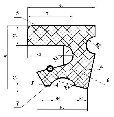
The utility model relates to a method for designing a combined sealing device used in low speed and heavy load conditions of a bearing. The half section of a sealing ring (4) is shaped like a Chinese character 'jiu' with one stroke to the left, and composed of a horizontal support (5), an inclined vertical support (6) and a beveled lip (7) which are naturally connected through three semicircular arcs R1, R2 and R3, a locking spring (3) is assembled in a semicircular groove of the sealing ring, then the sealing ring is installed into a left bracket-shaped inner casing (2), the end of the semicircular arc R2 is outward, and finally, a right bracket-shaped outer casing (1) is buckled outside the inner casing (2) at the end of the semicircular arc R2, and sealed for preventing the inner casing (2) from falling out of the outer casing (1). The sealing ring is clamped in a door-shaped structure including the outer casing and the inner casing to form the combined sealing device, therefore, a favorable guarantee is provided for maintaining the stiffness of the skeleton of the sealing ring, and the inclined vertical support and the beveled lip are in contact with the shaft shoulder of the inner ring, therefore, the dustproof and antifouling effect is better, the frictional contact area is reduced, and abrasion is reduced.

Description

[0001] technical field [0002] The invention belongs to the technical field of sealing, and in particular relates to a design method of a combined sealing device used in low-speed and heavy-load working conditions of bearings. [0003] Background technique [0004] Cylindrical roller bearings or tapered roller bearings under low-speed heavy-load conditions or harsh environments may cause premature failure of the above-mentioned bearings due to contamination of lubricating oil or grease. [0005] Usually, the sealing is implemented at the bearing box where the above-mentioned bearing is installed, and the sealing effect is not ideal. [0006] With the development of bearings to be unitized, if seals are added to the structure of the bearing itself, the operating conditions of the above-mentioned bearings will be better improved, thereby increasing the service life of the bearings, reducing maintenance and reducing costs. [0007] figure 1 It is a seal used in the ou...

Claims


Application Information

Patent Timeline
Patent Type & Authority Applications(China)
IPC IPC(8): F16C33/78
Inventor 常煜璞邓志杰宋吉祥王玉国魏闯张德颖
Owner LUOYANG BEARING SCI & TECH CO LTD
Learn More