
Electrorheological fluid damper with magnetic rotation and axial movement

An electro-variable and magnetic rotation technology, applied in non-rotational vibration suppression, vibration suppression adjustment and other directions, can solve the problems of fluid leakage in the fluid damper and the use restriction of the fluid damper, and achieves vibration suppression and large magnetic force. , the effect of large damping force

Inactive Publication Date: 2013-08-28
JIANGSU HONGSHUN SYNTHETIC FIBER TECH +1
View PDF6 Cites 0 Cited by
  • Summary
  • Abstract
  • Description
  • Claims
  • Application Information

AI Technical Summary

Problems solved by technology

[0002] The fluid damper is an effective structural damper, but during the working process of the fluid damper, there is a possibility of fluid leakage in the fluid damper. limit

Method used


Image

  • Electrorheological fluid damper with magnetic rotation and axial movement
  • Electrorheological fluid damper with magnetic rotation and axial movement
  • Electrorheological fluid damper with magnetic rotation and axial movement

Examples


Embodiment Construction

[0046] The present invention will be further described below in conjunction with the accompanying drawings.

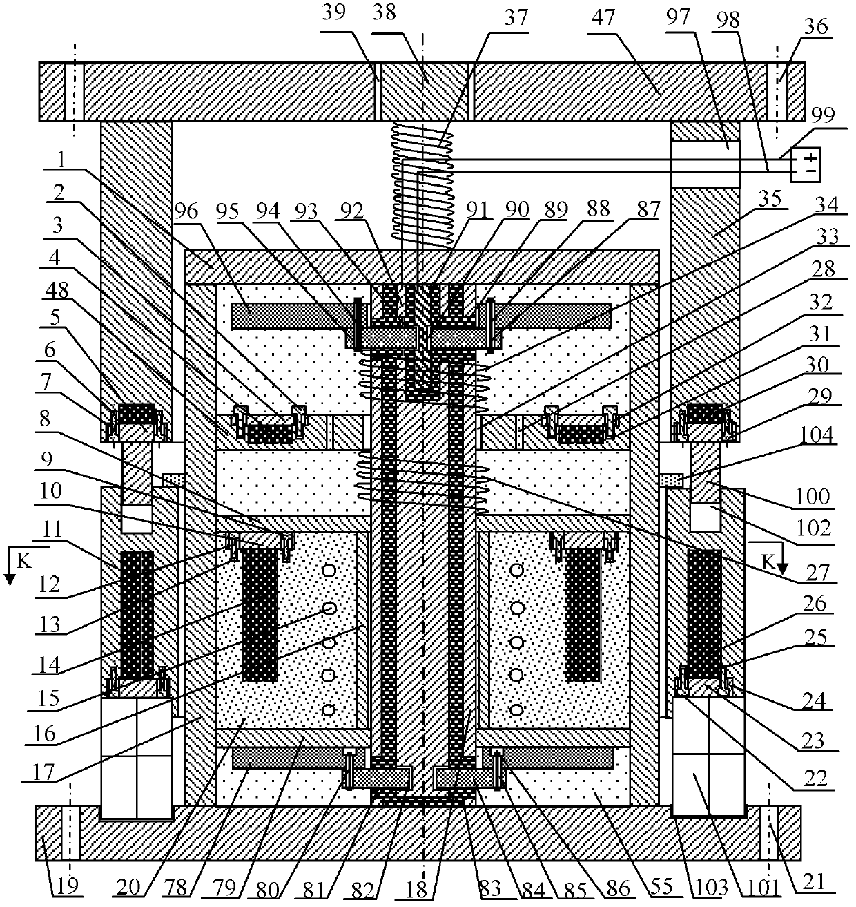
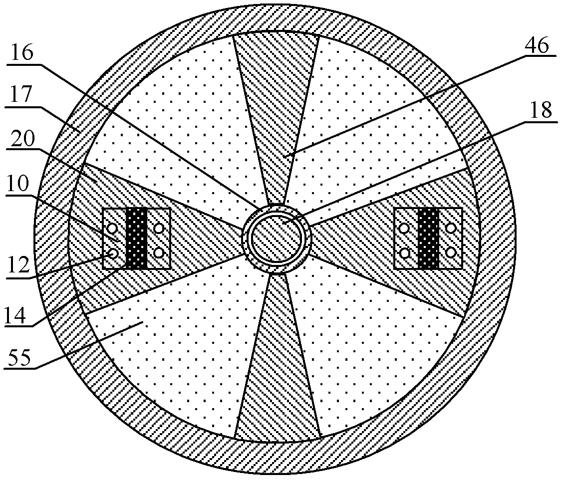
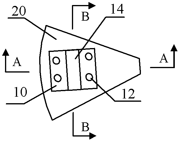
[0047] The present invention proposes a magnetic force rotation and axial motion electrovariant damper, which uses magnetic force to push the blades in the damper to rotate and the piston shaft to move. When the blades rotate (piston shafts), the damping fluid flows through the blades (pistons). Small round through hole (damping hole), energy is consumed when the damping fluid flows through the small round hole (damping hole) on the vane (piston), which has the effect of controlling vibration.

[0048] The following descriptions of embodiments of the invention are merely exemplary in nature, and are in no way intended to limit the application or uses of the invention.

[0049] The characteristic of the magnetic rotation and axial dynamic EPR damper is that the second circular spring 34 and the first circular spring 27 are removed simultaneously, and an effective magnetic...


PUM


Abstract

The invention relates to an electrorheological fluid damper with magnetic rotation and axial movement. A blade and a piston in the damper can be driven by magnetic force to make rotation and axial movement, respectively. During blade rotation and piston axial movement, an electrorheological fluid flows through a small round through hole on the blade and the piston to consume the energy so as to control rotation around the piston axis and vibration along the piston axis direction. In addition, the viscosity of the electrorheological fluid can be changed by changing the voltage between a positive electrode plate and a negative electrode plate according to the requirement for vibration control so as to realize active vibration control. Damping fluid is unlikely to be leaked from the damper by obviating the use of a dynamic sealing element.

Description

technical field [0001] The invention proposes a "magnetic rotation and axial dynamic current variable damper", which belongs to the field of structural vibration control. Background technique [0002] The fluid damper is an effective structural damper, but during the working process of the fluid damper, there is a possibility of fluid leakage in the fluid damper. limit. The present invention proposes a fluid damper. The damper does not use a dynamic seal, so it is not easy to cause liquid leakage failure. The damper can simultaneously control the linear displacement vibration along the axis of the hydraulic cylinder of the damper and the vibration of the rotational displacement around the axis of the hydraulic cylinder. vibration. Contents of the invention [0003] Technical problem: The purpose of the present invention is to propose a "magnetic rotation and axial dynamic electromorphic damper", which is especially suitable for structural vibration control under the cond...

Claims


Application Information

Patent Timeline
Patent Type & Authority Patents(China)
IPC IPC(8): F16F9/53
Inventor 韩玉林王芳
Owner JIANGSU HONGSHUN SYNTHETIC FIBER TECH
Learn More