Vibration inhibition control method and system for electric vehicle driving motor

A drive motor and vibration suppression technology, which is applied in the field of vibration suppression control of electric vehicle drive motors, can solve the problems of reducing vehicle operation response, poor effect, and inability to achieve instantaneous vehicle acceleration.

Inactive Publication Date: 2017-09-15
深圳市瀚路新能源汽车有限公司
View PDF5 Cites 7 Cited by
  • Summary
  • Abstract
  • Description
  • Claims
  • Application Information

AI Technical Summary

Problems solved by technology

[0003] In general, the existing technical solutions currently proposed cannot completely solve the problem, and the effect is not good, and most of the solutions adopted are to change the dynamic response of the vehicle to suppress the start

Method used


Image

  • Vibration inhibition control method and system for electric vehicle driving motor
  • Vibration inhibition control method and system for electric vehicle driving motor
  • Vibration inhibition control method and system for electric vehicle driving motor

Examples


Embodiment 1

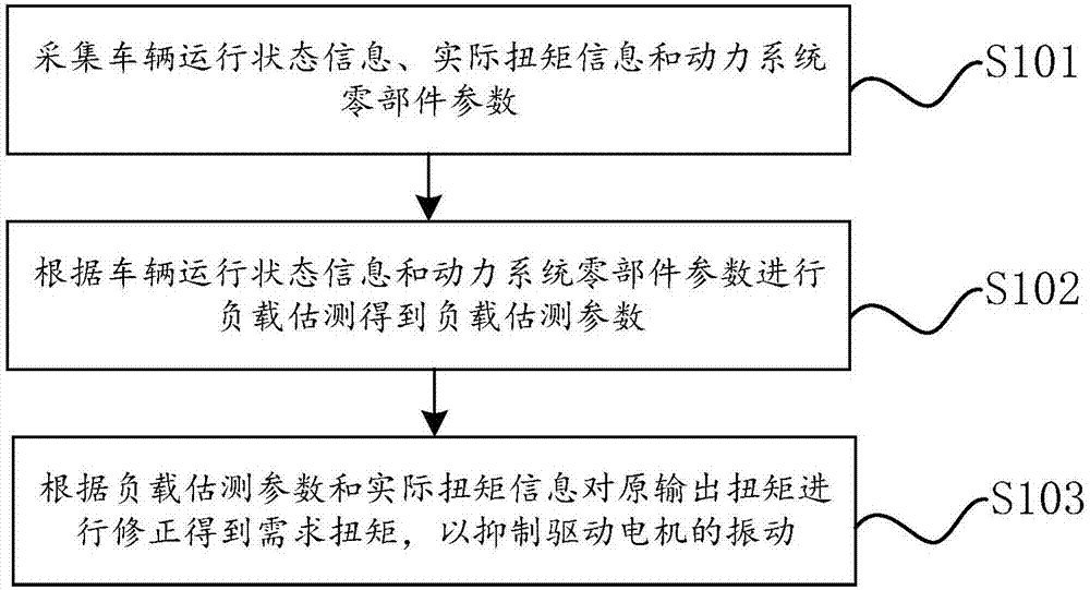
[0060] figure 1 It is a flowchart of a vibration suppression control method for an electric vehicle drive motor provided by an embodiment of the present invention.

[0061] refer to figure 1 , the electric vehicle drive motor vibration suppression control method includes:

[0062] Step S101, collecting vehicle running status information, actual torque information and power system component parameters;

[0063] Specifically, the actual torque information is the actual torque output value fed back by the drive motor, and the power system component parameters include drive motor, reducer, and drive shaft system parameters.

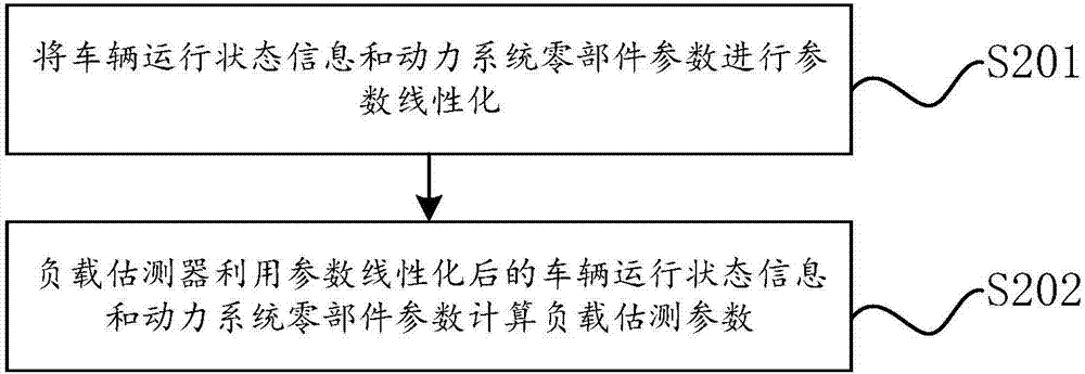
[0064] Step S102, performing load estimation according to the vehicle operating state information and the power system component parameters to obtain load estimation parameters;

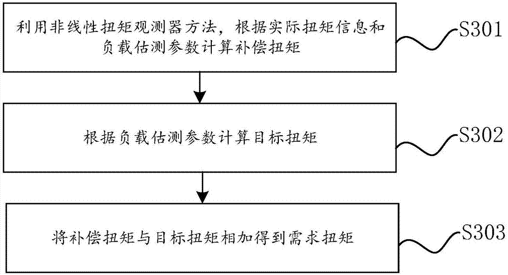
[0065] Step S103, correcting the original output torque according to the estimated load parameter and the actual torque information to obtain the required torque, so as to suppre...

Embodiment 2

[0102] Due to the instantaneous torque force transmission will produce a non-linear relationship between the transmission system and the traction force of the vehicle, resulting in more or less vibrations when the motor is driven. Therefore, the embodiment of the present invention mainly utilizes a nonlinear torque observer and a load estimator (inertia follower) to observe the torque at the moment of driving the electric vehicle motor, and perform torque compensation, so as to suppress and correct the occurrence of the momentary power transition. The vibration phenomenon improves the driving comfort of the vehicle.

[0103] Such as Image 6 As shown in this electric vehicle transmission system architecture diagram, when the motor produces torque instantly, the direct coupling between the motor and the reducer, as well as the coupling between the transmission shaft and the differential will all cause abnormal transmission due to the rigid transmission connection. Linear torqu...


PUM


Abstract

The invention provides a vibration inhibition control method and system for an electric vehicle driving motor. The vibration inhibition control method comprises the steps that vehicle operation state information, actual torque information and power system part parameters are collected; load estimation is conducted according to the vehicle operation state information and the power system part parameters to obtain load estimation parameters; and original output torque is corrected according to the load estimation parameters and the actual torque information to obtain required torque to inhibit vibration of the driving motor. The vibration inhibition control method and system can effectively inhibit vibration of the electric vehicle driving motor and shake generated through interactive operation between driving and power generation during vehicle travelling.

Description

technical field [0001] The invention relates to the technical field of drive motors, in particular to a vibration suppression control method and system for drive motors of electric vehicles. Background technique [0002] At present, most of the electric vehicle drive motors with a single-stage reducer are used. Since the single-stage reducer replaces the gearbox in the original traditional vehicle, the power transmission process is a direct coupling drive state, that is, the motor shaft is directly transmitted through the gear connection. to the reducer, so it is a rigid transmission connection. And when the moment of inertia of the motor is small, the moment the output torque of the motor changes, the transmission of this torque force will produce a nonlinear relationship between the transmission system and the traction force of the vehicle, resulting in more or less vibrations when the motor is driven. Phenomenon, especially when the vehicle is started and accelerated; th...

Claims


Application Information

Patent Timeline
IPC IPC(8): B60L15/20B60R16/02H02P21/05
CPCB60L15/20B60R16/02H02P21/05Y02T10/64Y02T10/72
Inventor 石亚文
Owner 深圳市瀚路新能源汽车有限公司
Why Eureka
Try Eureka