
A crane assembly

A crane and assembly technology, applied in the field of crane assembly, can solve the problems of relying on manual work, vibration at the top of the crane, deviation between the placement position and the target position, etc.

Active Publication Date: 2016-05-11
ANHUI JIANGHUAI AUTOMOBILE GRP CORP LTD
View PDF10 Cites 0 Cited by
  • Summary
  • Abstract
  • Description
  • Claims
  • Application Information

AI Technical Summary

Problems solved by technology

In practice, due to the movement and stop of the crane body, the top of the crane will often cause vibrations, which will cause deviations between the actual placement position of the goods and the target position after the crane lifts and moves the goods to the target position
[0004] In order to be able to place the goods to the target position when the vibration occurs during the lifting process of the crane, the following two methods are usually used to solve the problem: one is to wait for the vibration at the top of the crane to stop before placing the goods, which greatly reduces the operating efficiency The other is to adjust the piston stroke position of the hydraulic cylinder by the operator, thereby adjusting the lifting length and lifting angle of the crane, and then adjusting the placement position of the goods so that the goods can be placed at the target position, but This method mainly relies on manual work, and it also puts forward high requirements for the experience and proficiency of operators, and it is easy to cause safety problems when using manual operation
In addition, neither of the above two methods can fundamentally solve the problem of crane vibration, resulting in less practical application value

Method used


Image

  • A crane assembly
  • A crane assembly
  • A crane assembly

Examples


Embodiment Construction

[0032] In order to enable those skilled in the art to better understand the solutions of the embodiments of the present invention, the embodiments of the present invention will be further described in detail below in conjunction with the drawings and implementations.

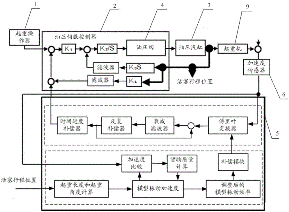
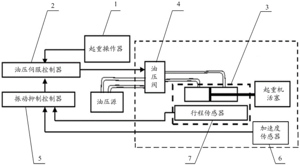
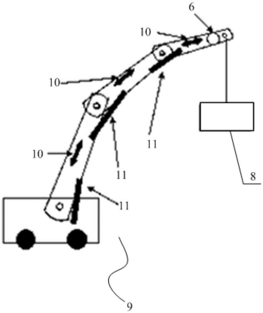
[0033] Such as figure 1 with figure 2 As shown, a crane assembly may include: a lifting operator 1, an oil pressure servo controller 2 and a plurality of oil pressure cylinders 3 arranged on the body of the crane 9, and oil pressure cylinders 3 are provided with oil pressure valves 4 , can also include: a vibration suppression controller 5 and an acceleration sensor 6; wherein, the acceleration sensor 6 can collect the actual acceleration during the lifting process of the crane 9; the vibration suppression controller 5 can generate vibration suppression that can offset the actual acceleration according to the actual acceleration signal, so that the hydraulic servo controller 2 controls the hydraulic valve 4 to...


PUM


Abstract

The invention discloses a crane assembly belonging to the technical field of industries. The crane assembly comprises a hoisting operator, an oil pressure servo controller and a plurality of oil pressure steam cylinders arranged on the crane body, wherein oil pressure valves are arranged on the oil pressure steam cylinders. The crane assembly further comprises a vibration inhibition controller and an acceleration sensor, wherein the acceleration sensor is used for acquiring the actual acceleration of a crane in the process of hoisting goods, and the vibration inhibition controller generates a vibration inhibition signal capable of counteracting the actual acceleration according to the actual acceleration so that the oil pressure servo controller controls the oil pressure valves to regulate piston stroke positions of the oil pressure steam cylinders according to a crane operating instruction set by the crane operator, so that at least one of a crane length and a crane angle of the crane can be regulated so that the goods are placed in a target position. The crane assembly is capable of effectively inhibiting the vibration generated in the process of hoisting the goods, so that the goods can be accurately placed in a target position.

Description

technical field [0001] The invention relates to the field of industrial technology, in particular to a crane assembly. Background technique [0002] A crane refers to a multi-action hoisting machine that lifts vertically and carries heavy objects horizontally within a certain range. With the development of industry, cranes are more and more widely used in the industrial field. In the field of industrial manufacturing, cranes are usually used to lift and move goods to the target location, and then place them. [0003] In the prior art, the crane assembly generally includes: a lifting operator, an oil pressure servo controller and a plurality of oil pressure cylinders arranged on the crane body, and oil pressure valves are arranged on the oil pressure cylinders. Among them, the lifting operator is used to set the lifting operation command, and the hydraulic servo controller is used to control the oil pressure valve to adjust the piston stroke position of the hydraulic cylind...

Claims


Application Information

Patent Timeline
Patent Type & Authority Patents(China)
IPC IPC(8): B66C23/62
Inventor 卫伟梅本修
Owner ANHUI JIANGHUAI AUTOMOBILE GRP CORP LTD
Learn More