Error compensation method for measuring film thickness of wafer of wafer stage

An error compensation and wafer stage technology, which is applied in the field of semiconductor manufacturing equipment, can solve problems such as inaccuracy, influence on accuracy, rough film thickness, etc., and achieve the effect of low communication requirements and easy implementation

Active Publication Date: 2012-07-11
TSINGHUA UNIV
View PDF4 Cites 6 Cited by
  • Summary
  • Abstract
  • Description
  • Claims
  • Application Information

AI Technical Summary

Problems solved by technology

However, when the wafer rotates, it is usually accompanied by errors such as end jumps and surface unevenness of the turntable, which affects the accuracy of the measurement
The film thickness value measured by the above method is rough and not accurate enough

Method used


Image

  • Error compensation method for measuring film thickness of wafer of wafer stage
  • Error compensation method for measuring film thickness of wafer of wafer stage
  • Error compensation method for measuring film thickness of wafer of wafer stage

Examples


Embodiment Construction

[0018] Embodiments of the present invention are described in detail below, examples of which are shown in the drawings, wherein the same or similar reference numerals designate the same or similar elements or elements having the same or similar functions throughout. The embodiments described below by referring to the figures are exemplary only for explaining the present invention and should not be construed as limiting the present invention.

[0019] The following disclosure provides many different embodiments or examples for implementing different structures of the present invention. To simplify the disclosure of the present invention, components and arrangements of specific examples are described below. Of course, they are only examples and are not intended to limit the invention. Furthermore, the present invention may repeat reference numerals and / or letters in different instances. This repetition is for the purpose of simplicity and clarity and does not in itself indicat...


PUM


Abstract

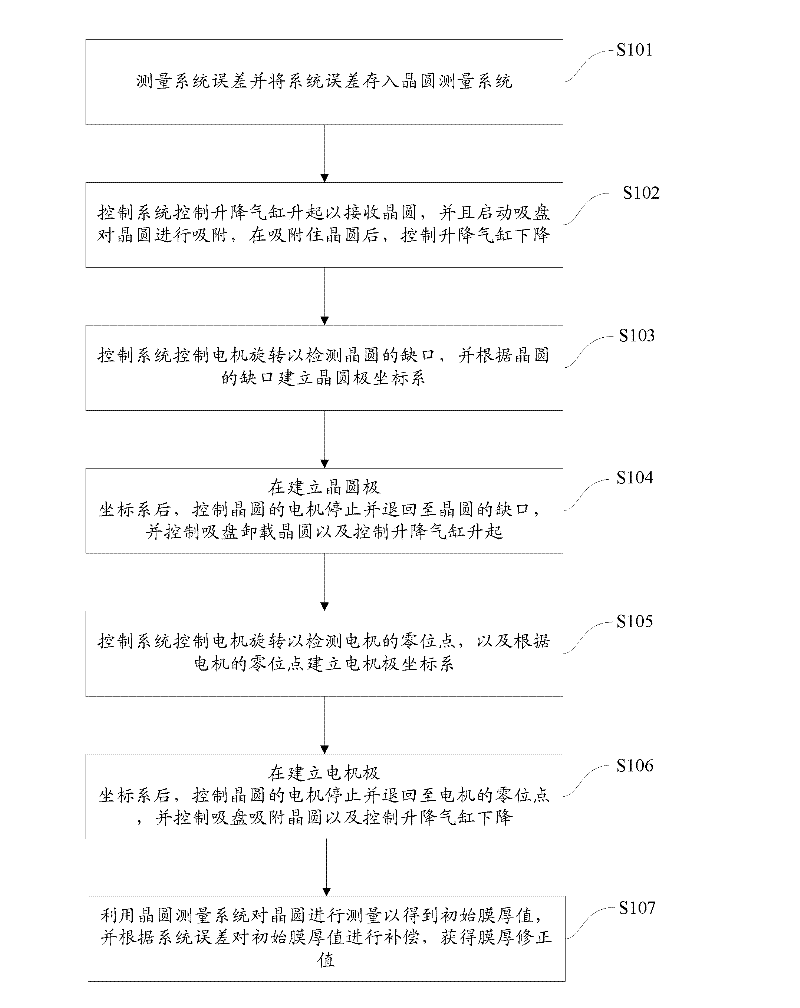
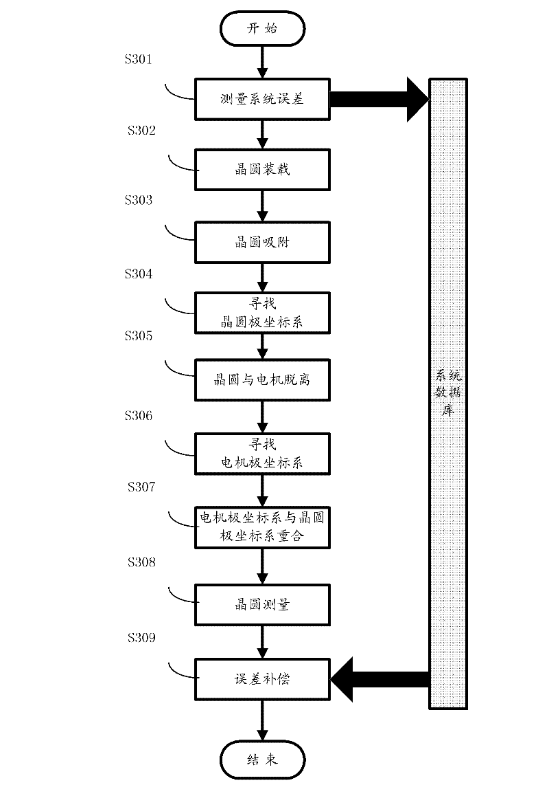
The invention provides an error compensation method for measuring film thickness of a wafer of a wafer stage. The error compensation method comprises the following steps of: measuring system errors; controlling a lifting cylinder to lift so as to receive the wafer, and starting a sucker to suck the wafer; controlling the lifting cylinder to lower; controlling a motor to rotate so as to detect the notch of the wafer, and establishing a wafer polar coordinate system according to the notch of the wafer; controlling the motor to stop after establishing the wafer polar coordinate system, returning to the notch of the wafer, controlling the sucker to unload the wafer, and controlling the lifting cylinder to lift; controlling the motor to rotate so as to detect a zero site of the motor, and establishing a motor polar coordinate system according to the zero site of the motor; controlling the motor to stop, returning to the zero site of the motor, controlling the sucker to suck the wafer and controlling the lifting cylinder to lower; and measuring the wafer by means of a wafer measuring system so as to acquire an initial film thickness value, and compensating the initial film thickness value according to the system errors. According to the error compensation method, the errors of the measured film thickness of the wafer can be compensated, and more accurate film thickness of the wafer can be acquired.

Description

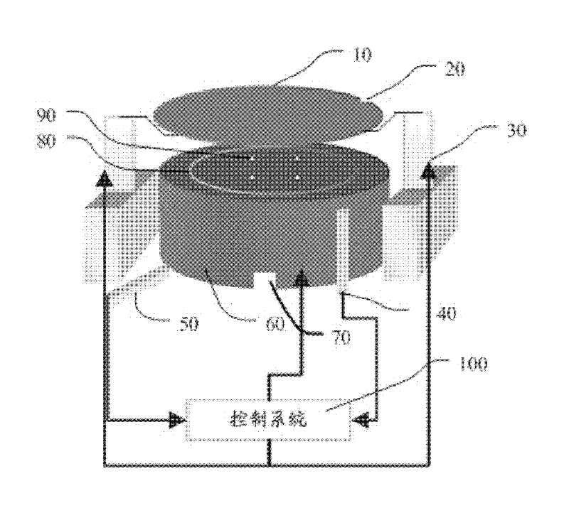
technical field [0001] The invention relates to the technical field of semiconductor manufacturing equipment, in particular to an error compensation method for measuring the film thickness of a wafer surface on a wafer table. Background technique [0002] After the wafer polishing is completed, it is necessary to grasp the flatness of the polished surface of the wafer. At this time, it is necessary to perform surface topography measurement on the wafer. Traditional measurement methods include two ways: the probe moves and the wafer does not move, or the probe does not move and the wafer moves. However, when the wafer rotates, it is usually accompanied by errors such as end jumps and surface unevenness of the turntable, thus affecting the accuracy of the measurement. The film thickness value measured by the above method is rough and not accurate enough. Contents of the invention [0003] The purpose of the present invention is to at least solve one of the above-mentioned...

Claims


Application Information

Patent Timeline
Patent Type & Authority Applications(China)
IPC IPC(8): G01B21/08
Inventor 赵乾门延武李弘恺余强孟永钢路新春
Owner TSINGHUA UNIV
Why Eureka
Try Eureka