Converter control system, converter control method and microgrid
A control system and converter technology, applied in the direction of AC network circuits, power transmission AC networks, circuit devices, etc., can solve the problems of low reliability, single structure, high technical requirements, and improve safety and reliability. The effect of low communication requirements and low communication requirements
- Summary
- Abstract
- Description
- Claims
- Application Information
AI Technical Summary
Problems solved by technology
Method used
Image
Examples
Embodiment 1
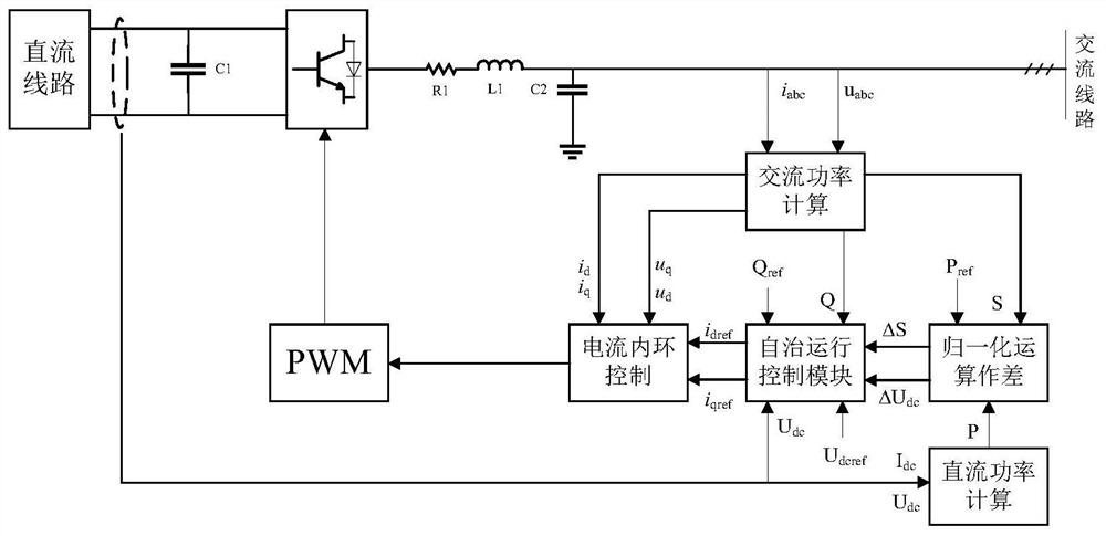
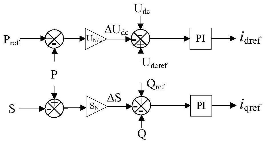
[0048] Inverter control system such as figure 2 , collect the DC line voltage U dc And input to the autonomous operation control module and the DC side active power calculation module to collect the DC voltage I dc And input to the active power calculation module on the DC side to collect the AC line voltage u abc and AC line current i abc And input the AC power measurement calculation module. In the normalization processing module, the apparent power S and the active power P are normalized and converted to obtain the apparent power deviation ∆S and input to the autonomous operation control module, and the reference active power P ref After normalized processing with the active power P, the difference is obtained to obtain the voltage deviation ∆U dc And input to the autonomous operation control module. The local output Q of the converter obtained in real time by the coordinate transformation power calculation module is input to the autonomous operation control module, ...
Embodiment 2
[0054] A control method corresponding to the converter control system in Embodiment 1, comprising the following steps
[0055] S01 according to the AC line current signal i abc and AC line voltage u abc Calculate the AC line current signal i abc The d-q axis component of the AC line voltage u abc The d-q axis component, apparent power S and reactive power Q of ;
[0056] S02 According to the reference active power P re、 Reference active power P ref Get the power deviation ∆S from the apparent power S, according to the reference active power P ref and the active power P to get the voltage difference ∆U dc ;
[0057] S03 will voltage deviation ∆U dc , The collected DC voltage U dc and DC voltage reference value U dcref Compare to get the d-axis current reference value i dref ;The reactive power deviation ∆S, reactive power Q and reactive power reference value Q ref Compare to get the q-axis current reference value i qref ;
[0058] S04 According to the q-axis cur...
Embodiment 3
[0067] The converter control system in Embodiment 1 is applied to the microgrid.
PUM
 Abstract
Description
Claims
Application Information
 - R&D
- Intellectual Property
- Life Sciences
- Materials
- Tech Scout
- Unparalleled Data Quality
- Higher Quality Content
- 60% Fewer Hallucinations
Browse by: Latest US Patents, China's latest patents, Technical Efficacy Thesaurus, Application Domain, Technology Topic, Popular Technical Reports.
© 2025 PatSnap. All rights reserved.Legal|Privacy policy|Modern Slavery Act Transparency Statement|Sitemap|About US| Contact US: help@patsnap.com


