Image processing method, device and system

A technology in images and images, applied in the field of image processing, it can solve problems such as poor effect and inability to ignore white, and achieve the effect of eliminating interference and good trapping effect.

Active Publication Date: 2012-07-11
FOUNDER INTERNATIONAL CO LTD +1
View PDF6 Cites 9 Cited by
  • Summary
  • Abstract
  • Description
  • Claims
  • Application Information

AI Technical Summary

Problems solved by technology

Because this method does not find the boundary of the white area, the white in the image cannot be ignored when laying the background, and there is no color gap between the white in the image and the ordinary color block when trapping, and the effect is poor

Method used


Image

  • Image processing method, device and system
  • Image processing method, device and system
  • Image processing method, device and system

Examples


Embodiment approach 1

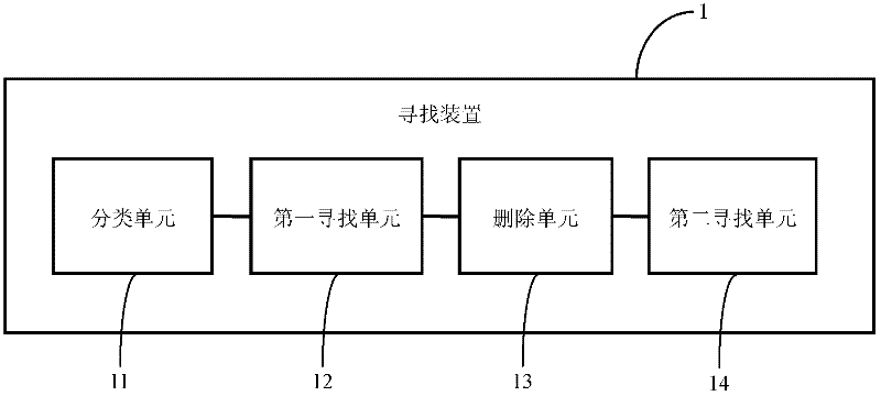
[0055] This embodiment describes a device and method for finding the boundary of a color block region in an image. Such as figure 2 As shown, the device 1 includes a classification unit 11 , a first search unit 12 , a deletion unit 13 and a second search unit 14 .

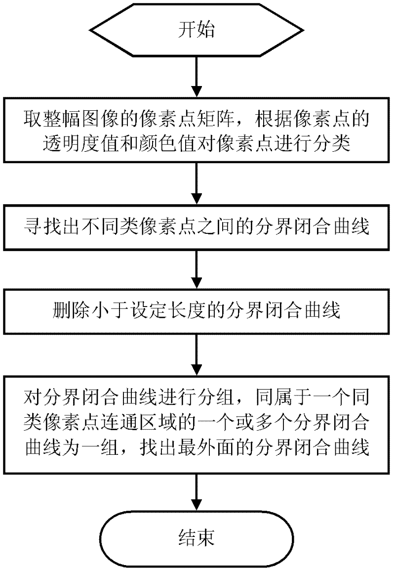
[0056] The classification unit 11 is used to obtain the pixel point matrix of the entire image, and classify the pixel points according to their transparency value and color value. The first finding unit 12 is used to find out the boundary closed curves between different types of pixel points. The deleting unit 13 is used for deleting the boundary closed curve smaller than the set area based on the circumference of the boundary closed curve. The second searching unit 14 is used for grouping the boundary closed curves, one or more boundary closed curves belonging to the same pixel point connected region are grouped together, and the outermost boundary closed curve is found to form a polygon.

[0057] Such as i...

Embodiment approach 2

[0066] This embodiment describes an image bottom laying system and method. Such as Figure 5 As shown, the system includes a searching device 1 , a filling device 2 , an associating device 3 and a laying device 4 .

[0067] The finding device 1 adopts the finding device described in the first embodiment, and is used to find the region boundaries of the color blocks in the image. The filling device 2 is used for filling white in the area of ​​the opaque white block, and filling corresponding colors in the area of ​​other color blocks. The associating means 3 is used for associating all color blocks with the image. The bottoming device 4 is used for traversing all the color blocks, if the color block is an opaque white area in the image, no bottoming is performed on the color block, otherwise, the bottoming is performed on the color block.

[0068] Such as Image 6 As shown, adopting above-mentioned system to carry out the method for laying the ground of image comprises the ...

Embodiment approach 3

[0075] This embodiment describes an image trapping system and method. Such as Figure 7 As shown, the system includes a searching device 1 , a filling device 2 , an associating device 3 and a trapping device 5 .

[0076] The functions of the searching device 1 , filling device 2 and associating device 3 are the same as those of the searching device 1 , filling device 2 and associating device 3 described in Embodiment 2. Trapping device 5 is used for traversing all color blocks, and judges the trapping mode between two regional blocks; If one of the color blocks is an opaque white block, then continue to judge whether another color block and the opaque white block belong to the same image, If yes, no color trapping will occur, otherwise color trapping will occur; if one of the color blocks is not an opaque white block, normal trapping will be performed.

[0077] Such as Figure 8 shown, using Figure 7 The method by which the illustrated system traps an image includes the f...


PUM


Abstract

The invention relates to a searching method for a regional boundary of a color block in an image. The method comprises the following steps of: taking a pixel point matrix of an entire image; classifying pixel points according to transparency values and color values of the pixels; searching boundary closed curves between different types of pixel points; finally grouping the boundary closed curves, wherein one or more boundary closed curves which belong to a communication region of the same type of pixel points to form a group to construct a polygon; and finding out the outermost boundary closed curve, wherein the polygon is the regional boundary of the color block. The invention also relates to a searching device for the regional boundary of a white block in the image and image bottoming and trapping method and system on the basis. The regional boundary of the white block in the image is additionally searched, so that the white region in the image is neglected during bottoming; color transfer trapping occurs when a normal color block meets white in the image; meanwhile, the interference of a small white region in the image is eliminated; and the trapping effect is better.

Description

technical field [0001] The invention belongs to the technical field of image processing, and in particular relates to a method and device for finding the boundary of a color block region in an image, and a method and system for laying and trapping on the basis thereof. Background technique [0002] In the prior art, there are methods for finding out transparent, translucent and opaque regions in an image, but there is no method for finding out white regions in an image. Therefore, the white area in the image cannot be ignored when laying the background, resulting in a poor laying effect; there is no color gap between the ordinary color block and the white area in the image during automatic trapping, resulting in inaccurate overprinting. The bottom layer refers to laying a layer of bottom color under all non-transparent color blocks, so that the effect will be better when printed on some transparent materials, and the transparent part does not need to be bottomed, and custome...

Claims


Application Information

Patent Timeline
Patent Type & Authority Applications(China)
IPC IPC(8): H04N1/58H04N1/56G06T7/00
Inventor 尹慧张琴
Owner FOUNDER INTERNATIONAL CO LTD
Why Eureka
Try Eureka