
Press drive and method for generating a stroke motion of a tool mounting by means of a press drive

A supporting device and press technology, which is applied in the direction of presses, transmissions, stamping machines, etc., can solve problems such as structural space constraints, achieve solid cost, and avoid the effect of switching mechanisms

Active Publication Date: 2012-07-11
TRUMPF WERKZEUGMASCHINEN GMBH & CO KG
View PDF6 Cites 1 Cited by
  • Summary
  • Abstract
  • Description
  • Claims
  • Application Information

AI Technical Summary

Problems solved by technology

However, the construction space is generally limited in the direction of the motor axis, so that the rotor-magnet enlargement is only possible in the radial direction

Method used


Image

  • Press drive and method for generating a stroke motion of a tool mounting by means of a press drive
  • Press drive and method for generating a stroke motion of a tool mounting by means of a press drive
  • Press drive and method for generating a stroke motion of a tool mounting by means of a press drive

Examples


Embodiment Construction

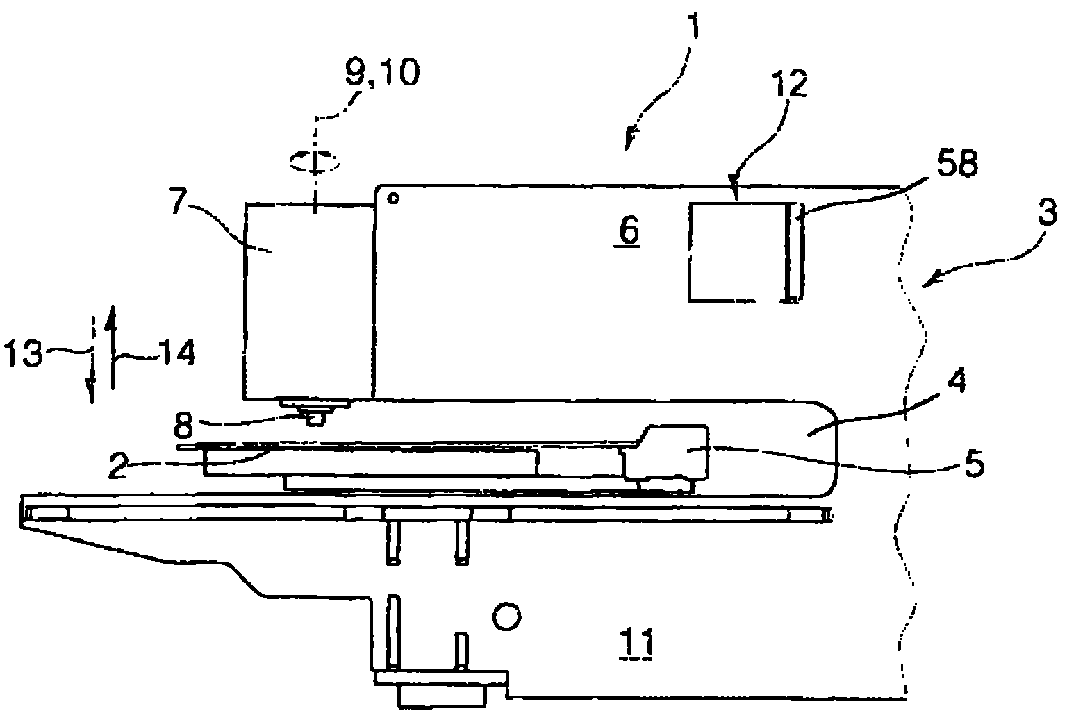
[0054] figure 1 A machine tool 1 for punching and / or forming a plate-shaped workpiece in the form of a plate 2 is shown. The machine tool 1 has a C-shaped frame 3, and a traditional coordinate guiding device 5 is provided in the jaw 4 of the frame. A press driver 7 is provided on the end of the upper arm 6 of the frame 3. A processing die configured as a punching die 8 can be moved up and down along the stroke axis 9 relative to the plate 2 supported on the coordinate guide 5 with the aid of the press drive 7. In addition, the processing die 8 can be rotationally adjusted by means of a press drive 7 about a rotational adjustment axis 10 coincident with the stroke axis 9. A mold support device (not shown) for the second mold is provided on the lower arm 11 of the frame 3 and opposite to the press driver 7.

[0055] The digital machine control device 12 is used to control all the drives of the machine tool 1.

[0056] In order to perform the punching or forming process of the shee...


PUM


Abstract

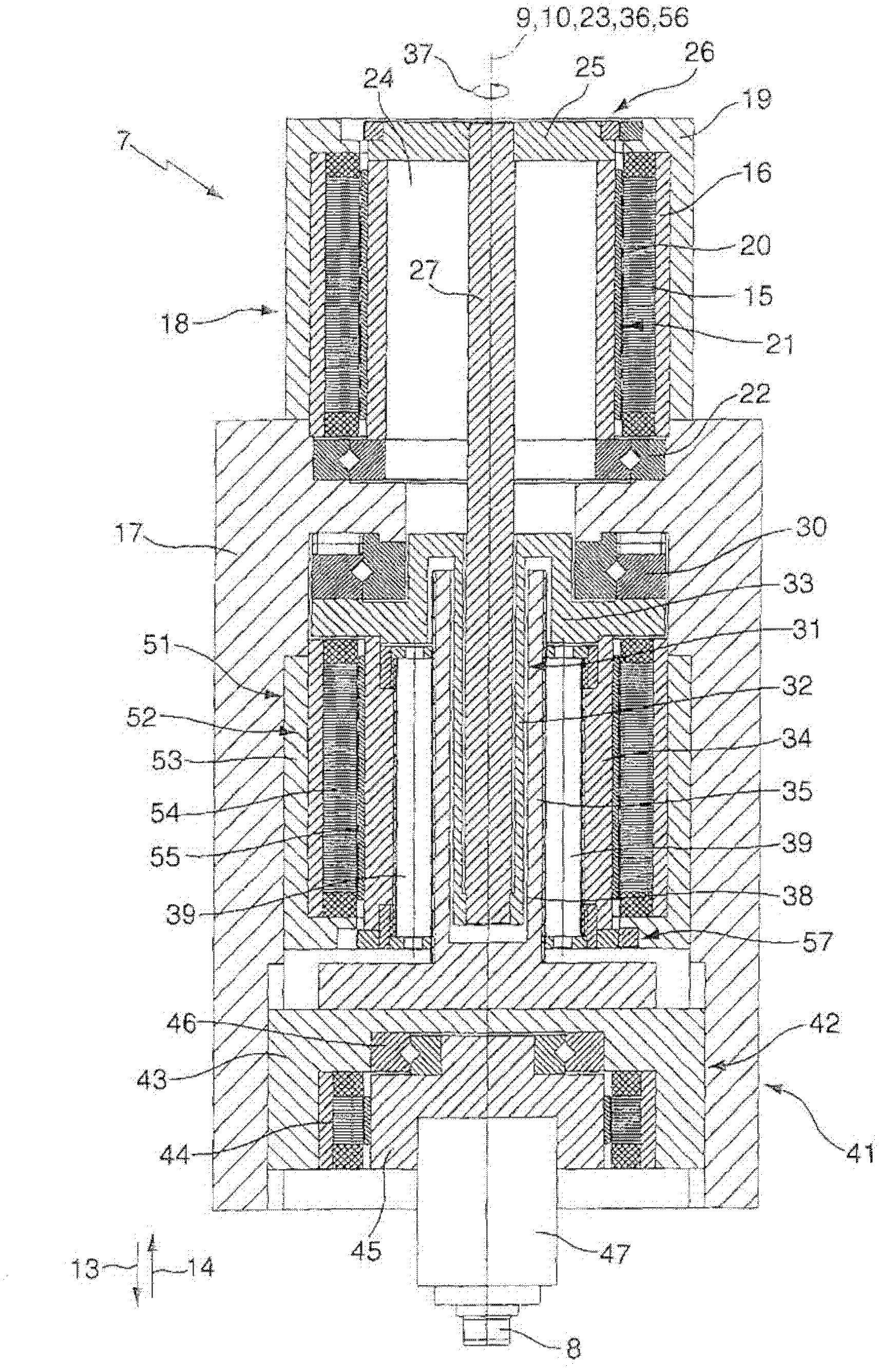
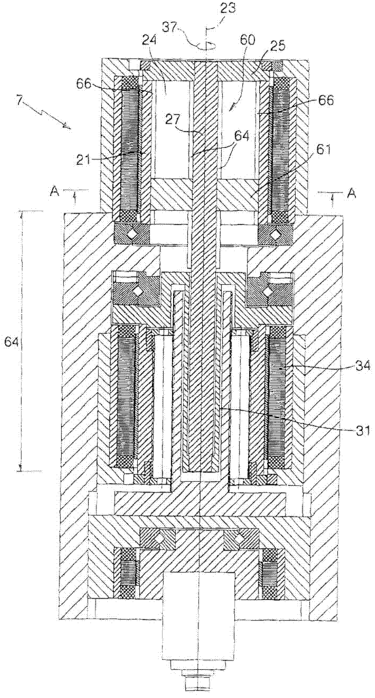
The invention relates to a press drive (7) comprising a press drive motor (18) drivingly connected to a tool mounting (47) by means of a coupling having a coupling element (25, 34) on the motor side and on the tool mounting side. In order for a press drive (7) to have high dynamic performance, an elastic connecting element (27, 31) is connected between the coupling element (25) on the motor side and the coupling element (34) on the tool mounting side, and a controllable delay device (51) engages with the coupling element (34) on the tool mounting side. A change in motion of the coupling element (34) on the tool mounting side introduced by means of the press drive motor (18) can be at least partially delayed by means of the delay device (51) in a controlled manner by deforming the elastic connecting element (27, 31).

Description

Technical field [0001] The present invention relates to a press drive, by means of which a mold supporting device can be moved in a stroke motion, wherein the press drive includes at least one press drive motor, which is provided with a motor-side and The coupling device of the coupling element on the mold supporting device side is drivingly connected with the mold supporting device. [0002] The invention also relates to a method for generating a stroke movement of a mold support device by means of a press drive having at least one press drive motor, which is provided with a coupling element on the motor side and the mold The coupling device of the coupling element on the support device side is drivingly connected to the mold support device, wherein a movement change of the coupling element on the mold support device side is introduced when the stroke movement is generated by the press drive motor. Background technique [0003] In the manufacture of machine tools, press drives wi...

Claims


Application Information

Patent Timeline
IPC IPC(8): B21D28/00B21D28/20B30B1/18F16H25/22
CPCF16H25/2252F16H2025/2078B30B1/18
Inventor C・施密特
Owner TRUMPF WERKZEUGMASCHINEN GMBH & CO KG
Learn More