Automatic forming combined firework barrel

A technology for automatic forming and firecracker barrels, applied in firecrackers and other directions, can solve the problems of easy falling of mud bottom, complicated assembly process, high labor intensity, etc., and achieve the effect of convenient automatic assembly line production, stable product performance and high labor intensity.

Inactive Publication Date: 2011-01-19
项友健
View PDF8 Cites 1 Cited by
  • Summary
  • Abstract
  • Description
  • Claims
  • Application Information

AI Technical Summary

Problems solved by technology

[0005] Compared with the invention patent of the one-time forming composite fireworks barrel of the prior art, the automatically formed combined fireworks barrel of the present invention has the following advantages: (1) Since the fireworks barrel is mainly composed of two independent parts, the barrel seat and the bobbin tube It is made of plug-in connection, which is convenient for installing lead wires. The bobbins are also connected by bobbin connectors. There is space between the bobbins, and they are not bonded and molded into a whole, so they are light in weight and suitable for large fireworks. It is also convenient to transport by making firecrackers of various numbers and fireworks of various sizes and height specifications; (2) because the bobbin 3 of the firecracker cylinder body and the firecracker cylinder body seat 2 can all be plastic one-time injection molding, it is convenient Automatic assembly line production overcomes the need to manually bundle and glue individual paper tubes, wrap the periphery with yellow cardboard or kraft paper, and use mud bottoms for multiple processing and molding. The assembly process of this handmade bundled combined fireworks is complex and labor intensive High strength, low production efficiency, high cost, and defects such as loose and falling mud bottom

Method used


Image

  • Automatic forming combined firework barrel
  • Automatic forming combined firework barrel
  • Automatic forming combined firework barrel

Examples


Embodiment Construction

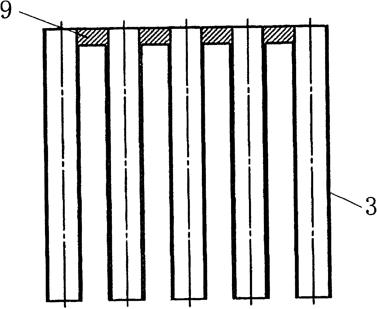
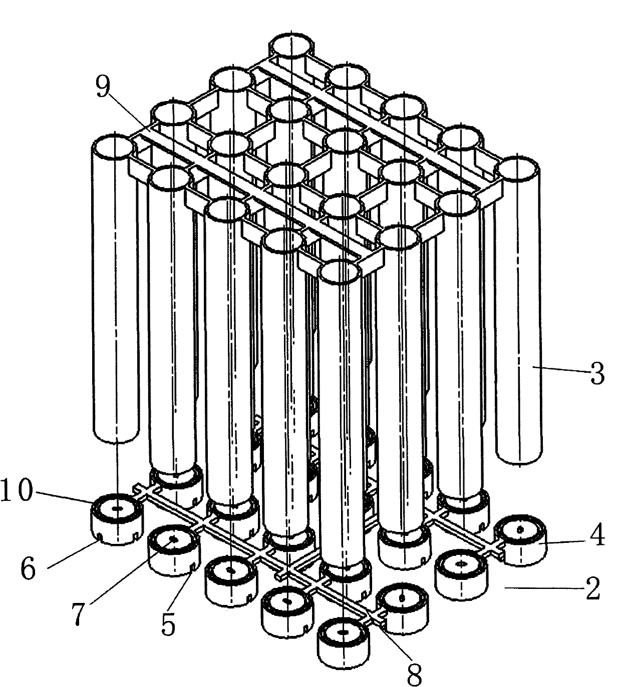
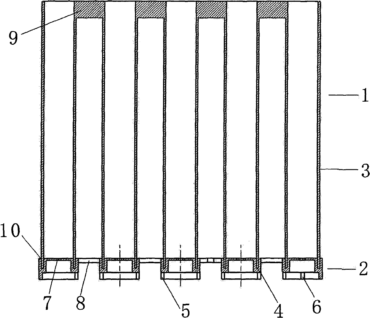
[0014] Such as figure 1 As shown: the automatic forming combined firecracker barrel of the present invention is mainly composed of a firecracker barrel 1, a string fire hole 7, and a fire string lead groove 5, and is characterized in that: the firecracker barrel 1 is mainly composed of a firecracker barrel seat 2 and a bobbin tube 3. Two independent components are inserted and connected. The firecracker barrel seat 2 is mainly composed of a bobbin socket 4 and a bobbin socket connector 8 for connecting each bobbin socket 4. The bobbin socket 4 is provided with a circle for Just plug into the groove 10 of the bobbin 3, a stringer hole 7 is provided in the center of the upper bottom of the bobbin socket 4, and the lower part of the tube wall of the bobbin socket 4 is provided with a stringer lead groove (5, 6). Tube connectors 9 are also used to connect the tubes 3 .

[0015] figure 2 and image 3 It is a structural schematic diagram of a firecracker barrel seat 2 for automa...


PUM


Abstract

The invention discloses an automatic forming combined firework barrel, which is characterized in that: the firework barrel (1) mainly comprises two independent components, namely a firework barrel seat (2) and a barrel tube (3) which are connected by inserting; the firework barrel seat (2) mainly comprises a barrel tube socket (4) and a barrel tube socket connector (8); and the barrel tube socket(4) is provided with a circle of groove (10) for inserting the barrel tube (3), the bottom of the barrel tube socket (4) is provided with a serial fire hole (7), and the lower part of the tube wall of the barrel tube socket (4) is provided with serial fire lead slots (5 and 6). The firework barrel has the advantages that: 1, because the firework barrel mainly comprises the two independent components, namely the firework barrel seat and the barrel tube which are connected by inserting, the firework barrel is convenient to assemble a lead; a space is formed between the barrel tubes, so the firework barrel has light weight, is suitable for manufacturing large-sized fireworks of various specifications and is also convenient for transportation; and 2, the firework barrel can be formed by one-time injection molding, is convenient for automatic production, and overcomes the defects that the hand-made bundled combined fireworks have complex process, high labor intensity, low production efficiency, high cost and the like.

Description

technical field [0001] The invention belongs to the field of fireworks, in particular to an automatically formed combined fireworks barrel filled with fireworks medicine. Background technique [0002] The traditional production of this kind of combined fireworks is made by binding and gluing individual paper tubes by hand, then wrapping the outer part with yellow cardboard or kraft paper, and using the mud bottom for multiple processing. Complex, labor-intensive, low production efficiency, high cost, and the defect that the mud bottom is easy to loosen and fall. In order to change the backward production status of this handmade, the Chinese patent numbers in the prior art are 200720063127.3 and 200820053096.8. The patent for the invention of the combined firecracker barrel, although it has better solved the defects of complex assembly process, high labor intensity, low production efficiency and high cost of combining individual paper tubes with glue by hand, but due to the a...

Claims


Application Information

Patent Timeline
Patent Type & Authority Applications(China)
IPC IPC(8): F42B4/04
Inventor 项友健
Owner 项友健
Why Eureka
Try Eureka