Air cylinder

A cylinder and cylinder hole technology, applied in fluid pressure actuation devices, fluid pressure actuation system components, mechanical equipment, etc.

Inactive Publication Date: 2012-07-11
SMC CORP
View PDF5 Cites 7 Cited by
  • Summary
  • Abstract
  • Description
  • Claims
  • Application Information

AI Technical Summary

Problems solved by technology

However, the place where the cylinder is usually installed is often a very narrow place or a space restricted by other adjacent equipment. Therefore, the cylinder used in such a place is required to be shortened even a little in the axial direction without shortening the operating stroke.

Method used


Image

  • Air cylinder
  • Air cylinder
  • Air cylinder

Examples


Embodiment Construction

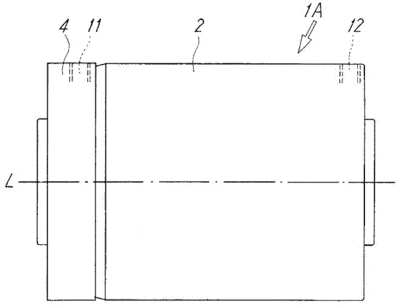
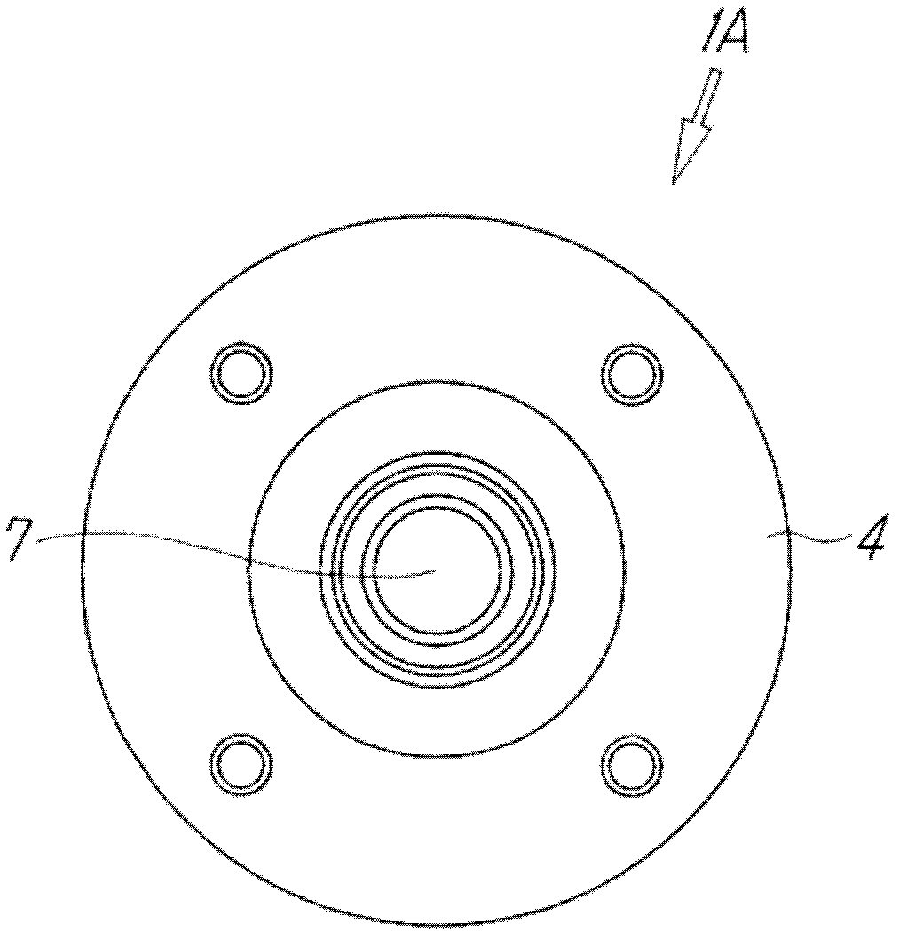
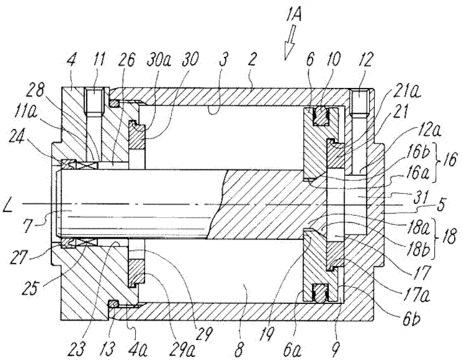
[0024] Figure 1 to Figure 3 The first embodiment of the air cylinder of the present invention is disclosed. This cylinder 1A comprises: cylindrical cylinder block 2, and it has circular cylinder bore 3 inside; Sliding in the cylinder hole 3 in the direction of the axis L; a piston rod 7 , the base end of which is connected to the piston 6 , and the piston rod 7 penetrates the end cover 4 slidably. In addition, this cylinder 1A includes: a first pressure chamber 8 formed between the above-mentioned piston 6 and the end cover 4; a second pressure chamber 9 formed between the above-mentioned piston 6 and the cylinder head cover 5; a first port 11 and a second port 12, the first port 11 is formed on the end cover 4 to supply compressed air into the first pressure chamber 8 or discharge compressed air from the first pressure chamber 8, the second port A portion 12 is formed on the cylinder head cover 5 for supplying compressed air into the second pressure chamber 9 or dischargin...


PUM


Abstract

An air cylinder having a simple and effective configuration to reduce the axial length and provide ease of processing. A sliding bearing that guides a piston rod is disposed at a position adjacent to a groove in which a rod packing is fitted. One end of the sliding bearing serves as the side wall of the groove and prevents displacement of the rod packing. The other end of the sliding bearing extends so as to cover part of a yenta of a first port. An orifice having a sectional area smaller than that of the yenta is formed at the position of the yenta by the sliding bearing.

Description

technical field [0001] The invention relates to an air cylinder which converts the energy of compressed air into linear motion for various operations. Background technique [0002] Cylinders operated by compressed air are extremely common, such as Figure 8 As schematically shown in , this cylinder includes: a piston 42 that slides in a cylinder bore 41 inside a cylinder body 40; a piston rod 43 that is connected to the piston 42; pressure chambers 44a, 44b that are formed in Both sides of the above-mentioned piston 42; two ports 45a, 45b, which supply compressed air into these pressure chambers or discharge compressed air from the above-mentioned pressure chambers, and alternately pass through these ports 45a, 45b to the above-mentioned pressure chambers 44a, 44b Compressed air is supplied and discharged, and various operations are performed by reciprocating the piston rod 43 by the piston 42 . [0003] This cylinder can easily obtain linear motion, so it is often used in ...

Claims


Application Information

Patent Timeline
Patent Type & Authority Applications(China)
IPC IPC(8): F15B15/14
CPCF15B15/1461F15B15/149F15B15/1433F15B21/14F15B15/14
Inventor 谷口长山田淳
Owner SMC CORP
Why Eureka
Try Eureka