Cutting blade

A technology of cutting blades and blades, applied in cutting tools, cutting equipment, gardening, etc., can solve problems such as low efficiency

Active Publication Date: 2012-07-18
FISKARS FINLAND OY
View PDF7 Cites 4 Cited by
  • Summary
  • Abstract
  • Description
  • Claims
  • Application Information

AI Technical Summary

Problems solved by technology

[0003] One of the problems associated with the above known cutting inserts is their low efficiency

Method used


Image

  • Cutting blade
  • Cutting blade
  • Cutting blade

Examples


Embodiment Construction

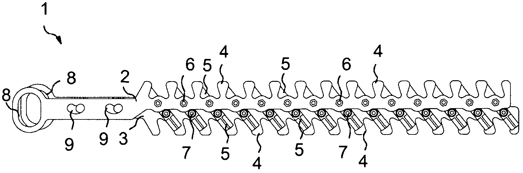
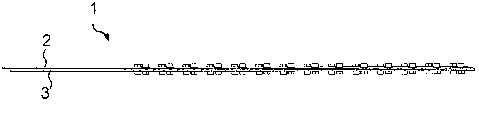
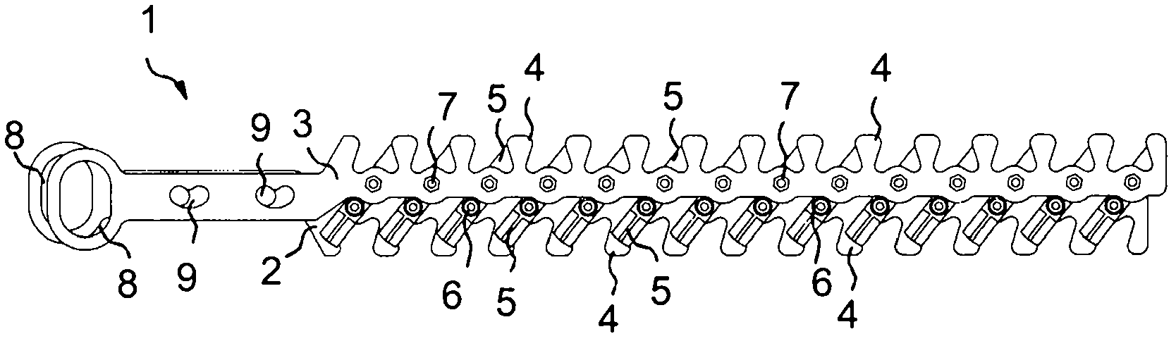
[0018] Figures 1 to 5 A first embodiment of a cutting insert 1 is illustrated. The cutting insert 1 comprises a first elongated frame part 2 and a second elongated frame part 3 . These frame sections may be made of suitable durable material such as steel. As is evident from the figures, the first frame part 2 and the second frame part 3 are arranged substantially parallel to each other.

[0019] There are projections 4 protruding from the first frame part 2 and the second frame part 3 in the transverse direction. These protrusions 4 cooperate with the blades 5 attached to the first and second frame parts 2 and 3 when the cutting blade 1 is in use, for example when cutting bushes.

[0020] The cutting insert 1 comprises a plurality of inserts 5 which, in the embodiment of the figures, are formed from generally rectangular pieces of a suitable material such as steel. Each blade 5 may be formed from a single piece whereby its upper end (as sharpened as possible) cooperates w...


PUM


Abstract

The present invention relates to a cutting blade (1) comprising: a first (2) and a second (3) elongated frame part, and projections (4) protruding from the first (2) and the second (3) elongated frame part in the cross direction. To provide an efficient cutting blade, the first (2) and the second (3) frame part are attached to each other by blades (5), the blades being individually attached to the first frame part (2) at first pivot points (6) and to the second frame part (3) at second pivot points (7) in such a way that the opposite ends of the blades (5) protrude from the first (6) and second (7) pivot points, respectively, in the cross direction of the frame parts (2, 3). The first (2) and the second (3) elongated frame part are movable relative to each other to rotate the blades (5) around the first (6) and second (7) pivot points and to generate a cutting movement between each end of the blade (5) and projection (4) approaching each other.

Description

technical field [0001] The present invention relates to a cutting insert which is described below mainly by reference to a cutting insert for a hedge trimmer. However, it should be noted that the cutting insert according to the invention may also be suitable for other situations. Background technique [0002] Cutting blades for hedge trimmers are known from the prior art, for example comprising a first elongated frame part and a second elongated frame part. There are projections extending from the first frame portion and the second frame portion in a lateral direction. When the frame parts of the cutting blades are moved back and forth relative to each other in their longitudinal direction during use, branches that have stood between the lugs are cut due to the pressing force between the lugs. [0003] One of the problems associated with the known cutting inserts described above is their low efficiency. In practice, the force required to generate the reciprocating motion ...

Claims


Application Information

Patent Timeline
Patent Type & Authority Applications(China)
IPC IPC(8): A01G3/04
CPCA01G3/053A01G3/04
Inventor P·马萨林J·胡赫塔拉M·帕洛黑莫F·芒努松
Owner FISKARS FINLAND OY
Why Eureka
Try Eureka