
Magnetic control chemical chain combustion reaction device and method

A chemical chain combustion and reaction device technology, applied in the direction of exothermic chemical reaction heat generation, using non-combustion exothermic chemical reaction to generate heat, heating devices, etc., can solve the problem of reducing gas fuel combustion efficiency and reducing non-magnetic porous oxygen Problems such as effective conversion of solid and magnetic porous oxygen carriers, uneven distribution of porous oxygen carrier particles, etc.

Active Publication Date: 2017-11-28
NORTHEASTERN UNIV
View PDF7 Cites 2 Cited by
  • Summary
  • Abstract
  • Description
  • Claims
  • Application Information

AI Technical Summary

Problems solved by technology

This movement behavior causes the uneven distribution of porous oxygen carrier particles, thereby reducing the effective conversion of non-magnetic porous oxygen carrier and magnetic porous oxygen carrier. In addition, the reduced magnetic carrier cannot be separated in time, so that the gas fuel cannot participate in the reduction. The oxygen carrier is fully contacted, reducing the combustion efficiency of gas fuel

Method used


Image

  • Magnetic control chemical chain combustion reaction device and method
  • Magnetic control chemical chain combustion reaction device and method

Examples


Embodiment 1

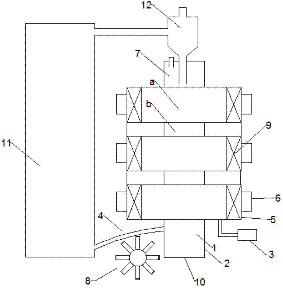
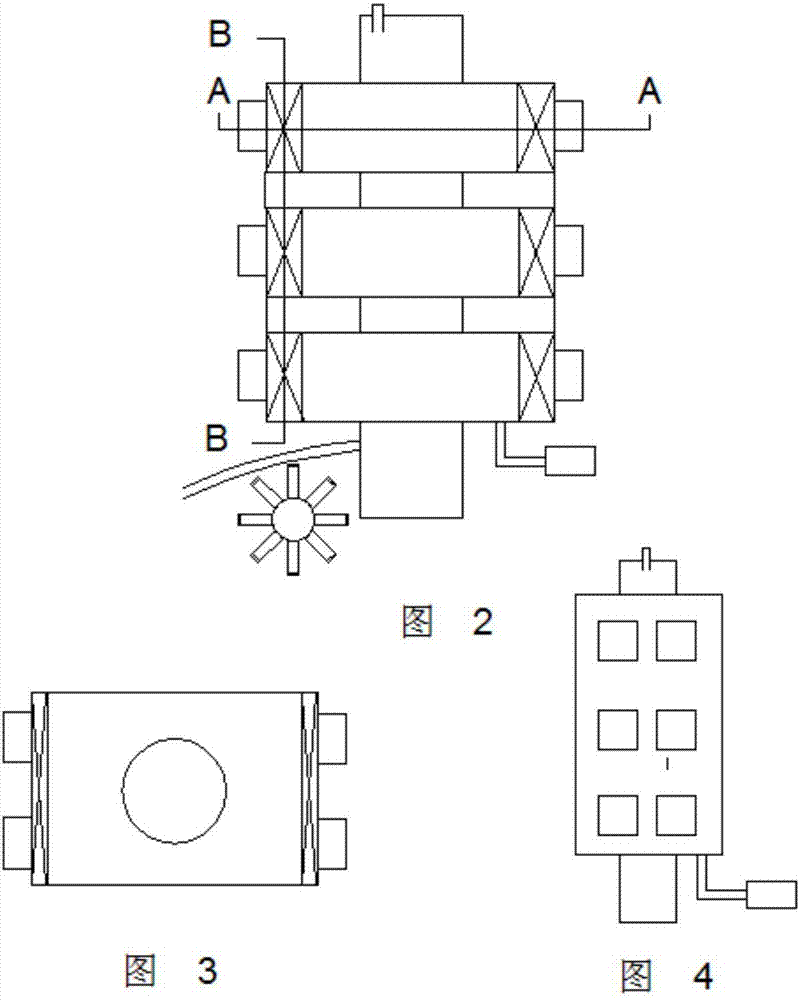
[0043] The embodiment of the present invention is illustrated by taking a pulsed magnetic field coupled rotating magnetic field with three magnetic field generators as an example to control the chemical chain reduction reaction. Its structure is as follows Figure 1~4 As shown, the device includes a fuel reaction channel 2, an air distribution plate 10 is arranged at the bottom of the fuel reaction channel 2, a discharge pipe 4 is provided on the left, and a rotating magnetic field separation device 8 is provided at the lower end of the discharge pipe 4 . Three magnetic field generating devices 5 are arranged between the front end and the end of the fuel reaction channel 2, each of the magnetic field generators 5 includes a cavity, the fuel reactor pipeline 2 passes through the middle of the cavity, and the fuel reaction channel 2 is The magnetic field generator 5 is divided into a section with a magnetic field and section b without a magnetic field. Exciting coils 9 are wound...


PUM


Abstract

The invention relates to a magnetic control chemical chain combustion reaction device and method and belongs to the field of chemical chain combustion. The magnetic control chemical chain combustion reaction device comprises a fuel reaction channel, an air reaction channel, a cyclone separator, three magnetic field generators and a rotary magnetic field generation device, wherein a body of each magnetic field generator is a cavity; the two ends of each cavity are wound with magnet exciting coils; the magnetic field generators are horizontally arranged; the fuel reaction channel penetrates through the cavities of all the magnetic field generators and is divided into a magnetic field section a and a non-magnetic field section b by the magnetic field generators; and the rotary magnetic field generation device makes magnetic oxygen carriers reduced in the fuel reaction channel rapidly enter the air reaction channel by the magnetic force function. Compared with a traditional chemical chain CH4 gas fuel combustion device, the problem of oxygen carrier agglomeration is solved, and deoxidation carriers are subjected to movement and a reaction in the reaction device automatically, controllably and efficiently.

Description

technical field [0001] The invention relates to a device and method for a magnetically controlled chemical looping combustion reaction, belonging to the field of chemical looping combustion. Background technique [0002] Chemical looping combustion technology is a revolutionary new combustion method, which decomposes the traditional combustion of direct reaction between fuel and air into two gas-solid reactions with the help of oxygen carrier. From a thermodynamic point of view, the combustion process is a process in which the working medium (oxygen carrier) of the thermodynamic system consumes a large amount of energy. The biggest potential to solve energy utilization and environmental problems is the combustion process, and chemical loop combustion breaks the traditional combustion technology and is a new and clean combustion technology. [0003] Chemical looping combustion reactors are divided into air reactors and fuel reactors. The basic characteristic of the porous c...

Claims


Application Information

Patent Timeline
IPC IPC(8): F24J1/00F24V30/00
CPCF24V30/00
Inventor 李东刚王楠王坤王迪王强
Owner NORTHEASTERN UNIV
Learn More