

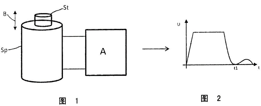
Method for actuating an electromagnetic actuator device having a coil
A technology for adjusting devices and coils, applied to electromagnets with armatures, electromagnets, valve devices, etc.
- Summary
- Abstract
- Description
- Claims
- Application Information
AI Technical Summary
Problems solved by technology
Method used
Image

Examples
Embodiment Construction
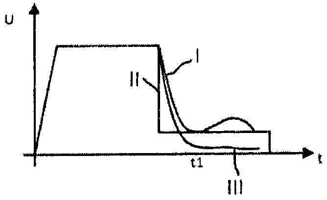
[0015] according to image 3 and 4 , a voltage is first applied to the coil of the Sp electromagnetic adjustment device, which causes a current to flow, which is large enough to set the non-permanently magnetic tappet in motion and then held in the extended position by an almost constant current, and then by Turning off the higher voltage ends the operation. This is shown by the curve denoted by I.
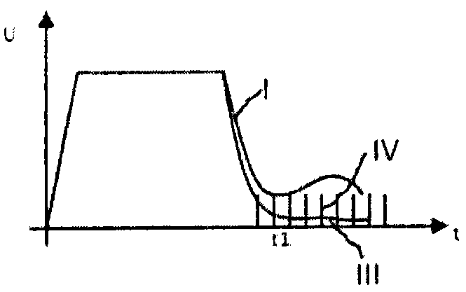
[0016] However, in the manner according to the invention, the voltage at the coil is not switched off, but is reduced to a value which on the one hand is not sufficient to operate the tappet again due to the resulting current, but on the other hand is large It is sufficient to magnetize the tappet so that due to its mechanically induced movement from the outside it induces a sufficiently high reverse voltage which can be detected with simple means.
[0017] here, image 3 Magnetizing energization with a nearly constant continuous current is shown denoted by III, while at Fig...
PUM
 Abstract
Description
Claims
Application Information