
High-precision small digital controlled lathe
A CNC lathe, high-precision technology, applied in the direction of automatic lathes/semi-automatic lathes, turning equipment, turning equipment, etc., can solve problems such as large contact area between slide table and guide rail, small size of lathe, and reduce processing efficiency, so as to improve processing accuracy and service life, high guiding accuracy, and improved vibration resistance
Patent Information
- Authority / Receiving Office
- CN · China
- Current Assignee / Owner
- Publication Date
- 2016-03-09
- Estimated Expiration
- Not applicable · inactive patent
Smart Images
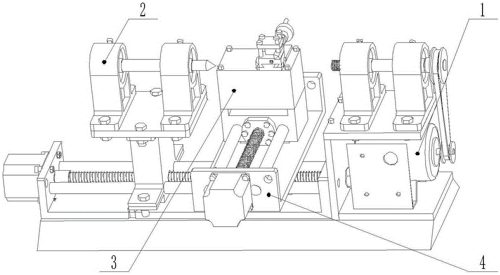
Figure 1 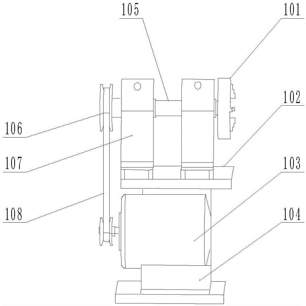
Figure 2 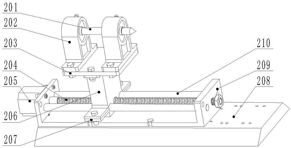
Figure 3
Abstract
Description
technical field
[0001] The invention relates to a high-precision small numerically controlled lathe, which belongs to the field of small mechanical processing equipment. Background technique
[0002] Small CNC lathes are CNC lathes with small dimensions. This type of CNC lathe is mainly used for processing small-sized high-precision workpieces and mass production of small workpieces. It is widely used in military enterprises, electronic appliances, machinery manufacturing, aviation, etc. Aerospace and other fields.
[0003] The guide rails of ordinary small CNC lathes usually adopt dovetail groove structure, and the iron chips are easy to accumulate in the chute during cutting, which increases the friction resistance with the slide table and reduces the processing efficiency. The contact area between the slide table and the guide rail is large, and the long The thermal deformation of the guide rail is easy to occur under long-term work. The overall volume of the lathe is sm...
Examples
Embodiment Construction
[0012] 1. See figure 1 , figure 2 , image 3 , Figure 4 , Figure 5 , the high-precision small CNC lathe provided by the present invention, the spindle motor base 104 in the spindle power mechanism 1 and the machine tool base 208 in the moving tailstock 2 are connected by bolts, and the lower ball screw 204 in the moving tailstock 2 is connected to the slide table 3 The lower lead screw nut 305 in the slide table 3 is connected by bolts, and the slide block 306 in the slide table 3 is connected with the knife rest cushion block 404 in the knife rest 4 by bolts.
[0013] 2. If figure 2 As shown, the chuck 101 is connected to the main shaft 105 by bolts, the main shaft support pad 102 is connected to the main shaft motor base 104 by bolts, the main shaft motor 103 is connected to the main shaft motor base 104 by bolts, and the main shaft 105 is connected to the pulley 106 by bolts. The wheel 106 is connected to the main shaft motor 103 through a belt 108, the main shaft ...