
Patsnap Eureka
For R&D, Patsnap Eureka makes reading and utilizing patents & technical documents easy.
Patsnap Eureka AIR
Designed for self-driven R&D workflows. Generate viable solutions, solve complex R&D challenges, empower your innovation with AI.

Patsnap Eureka Materials
Designed for material experts only. Revolutionize your material R&D, from search, analyze, to developing new materials.

TechResearch
Generate reliable direction feasibility study reports for your R&D in just a few steps.

TechSeek
Discover and master advanced knowledge NOW. Basics, ideas, possibilities, all at once.

TechMind
As an expert in R&D Theories, TechMind can generates customized viable solutions instantly.

TechRisk
Analyze your overall solution with one click, know your potential R&D risks in advance.

TechMonitor
Get weekly tech updates, stay abreast of the latest tech innovations and key insights.
Double-shaft radial flow reactor
A reactor, axial and radial technology, applied in the field of biaxial radial flow reactor, can solve the problems affecting the reaction efficiency, achieve the effect of improving the reaction efficiency, good reaction effect and prolonging the service life
- Summary
- Abstract
- Description
- Claims
- Application Information
AI Technical Summary
Problems solved by technology
Method used
Image

Examples
Embodiment 1
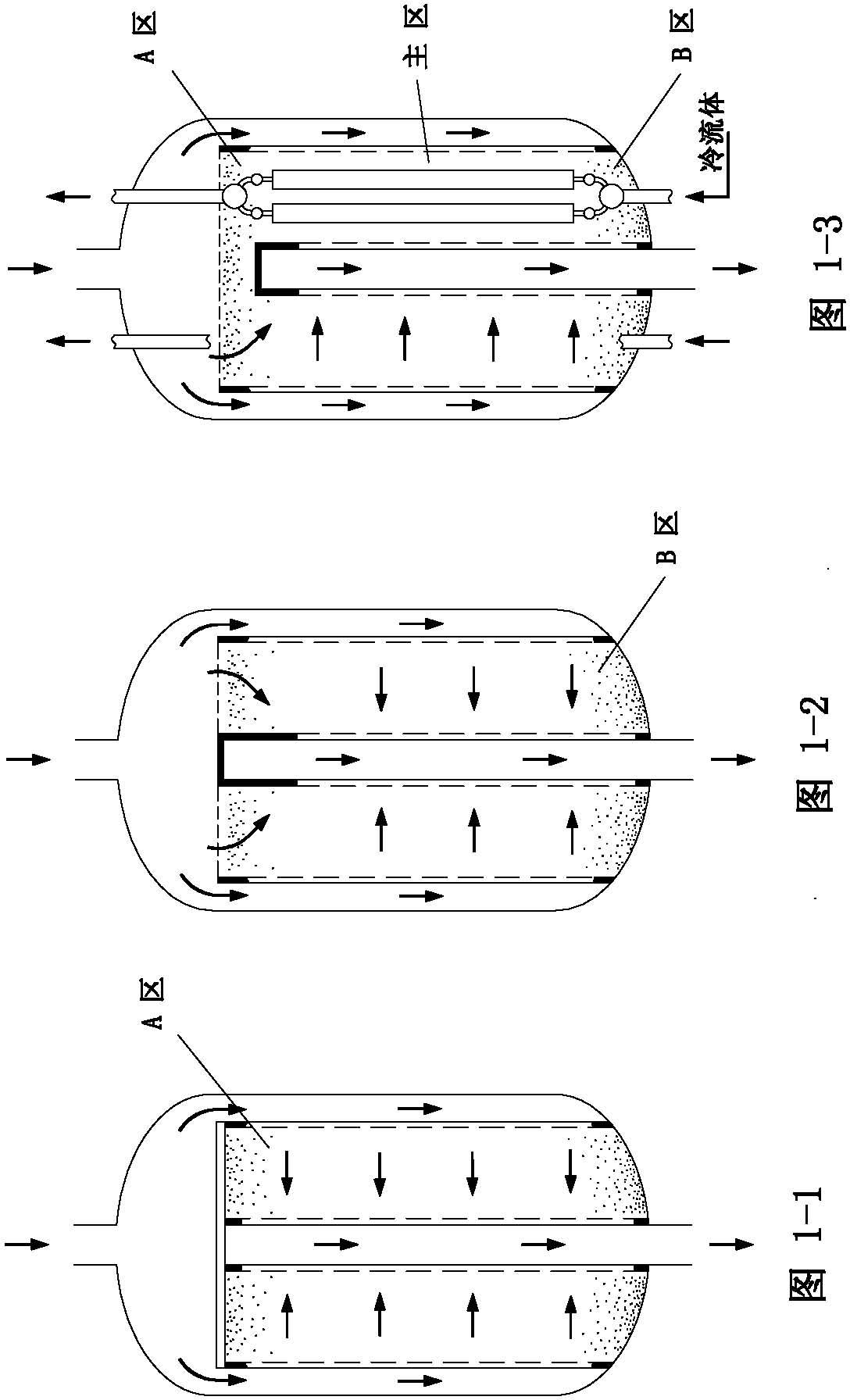
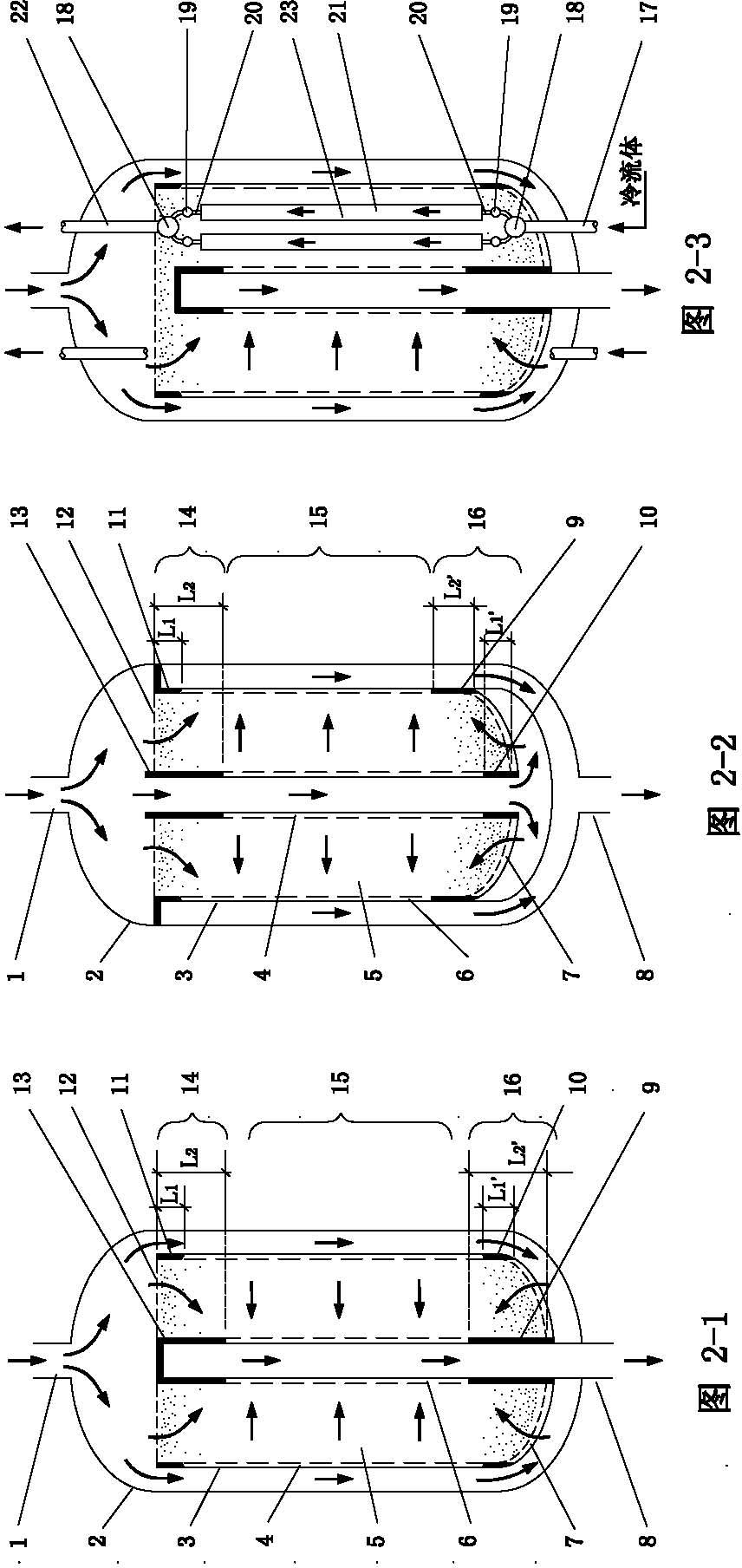
[0035] Such as diagram 2-1 , 3-3 shown.
[0036] A kind of biaxial radial flow reactor, it comprises shell 2 and reactor internal part 3, and reactor internal part 3 is positioned at shell 2, and described shell 2 is provided with reactor inlet 1 and reactor outlet 8, and reaction The internals 3 include a distribution cylinder 4 and a gas collection cylinder 6, a catalyst bed 5 is installed between the gas collection cylinder 6 and the distribution cylinder 4, the reactor outlet 8 communicates with the outlet end of the gas collection cylinder 6, and the inside of the reactor An upper axial reaction section 14 and a lower axial reaction section 16 are respectively formed on the upper end and the lower end of the member 3, and a radial reaction section 15 is formed between the upper axial reaction section 14 and the lower axial reaction section 16; The upper end of the catalyst bed 5 is equipped with a porous upper cover and a wire mesh 12, and the lower end is equipped with...
Embodiment 2
[0045] Such as Figure 2-2 , 3-4.
[0046] The difference between this embodiment and Embodiment 1 is that the distribution cylinder 4 of this embodiment is located in the gas collection cylinder, while the gas collection cylinder 6 of Embodiment 1 is located in the distribution cylinder 4, the reaction gas enters from the reactor inlet 1, and a part of the gas enters in the axial direction The flow mode passes through the porous upper cover and the wire mesh 12, enters the radial section 14 of the upper shaft to react with the catalytic bed layer, and then flows into the gas collector 6 of the outer ring. The reaction gas in the middle full radial reaction section is directly from the center of the reactor. The distribution cylinder 6 enters the gas collector through the middle full radial section 15 from the inside to the outside, and another part of the gas flows through the middle full radial section of the distribution cylinder 4 and directly enters the lower axial re...
Embodiment 3
[0048] Such as Figure 2-3 shown.
[0049] The difference between this embodiment and implementation one and two is that a heat transfer device 23 is also installed in the catalytic bed 5, and the heat transfer device 23 is composed of a heat transfer tube plate 21, a large header 18, a small header 19, a connecting pipe 20, a cooling The fluid inlet pipe 17 and the cooling fluid outlet pipe 22 are composed. The inlet and outlet ends of each heat transfer tube plate 21 are connected to the corresponding small headers 19 through their respective connecting pipes 20, and each small header 19 is connected to the corresponding large headers. 18 are connected, and the large header 18 is connected with the corresponding cooling fluid inlet pipe 17 or cooling fluid outlet pipe 22, such as Figure 2-3 shown. The heat removal device of this embodiment can be used in both the reactor with flow structure from outside to inside (Example 1), and also the reactor with flow structure from ...
PUM
 Abstract
Description
Claims
Application Information
 - R&D Engineer
- R&D Manager
- IP Professional
- Industry Leading Data Capabilities
- Powerful AI technology
- Patent DNA Extraction
Browse by: Latest US Patents, China's latest patents, Technical Efficacy Thesaurus, Application Domain, Technology Topic, Popular Technical Reports.
© 2024 PatSnap. All rights reserved.Legal|Privacy policy|Modern Slavery Act Transparency Statement|Sitemap|About US| Contact US: help@patsnap.com