Welding twist drill

A technology of twist drills and twist drills, which is applied in the direction of twist drills, etc., can solve problems such as the impossibility of drill bits, and achieve the effect of low price, good use effect and high cost performance

Inactive Publication Date: 2012-07-18
江海青
View PDF5 Cites 3 Cited by
  • Summary
  • Abstract
  • Description
  • Claims
  • Application Information

AI Technical Summary

Problems solved by technology

[0003] At present, there are many types and manufacturers of twist drills on the market, and it is hard to tell the good from the bad, but one thing is that it is almost impossible to buy a good drill with cheap money.

Method used


Image

  • Welding twist drill
  • Welding twist drill

Examples


Embodiment Construction

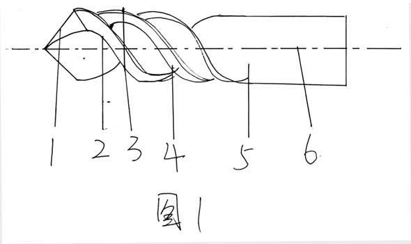
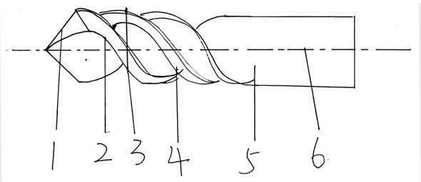
[0010] figure 1 Middle: Take a piece of high-quality high-speed steel for the cutting part (1) and the front twist part (2) of the drill head, and another piece of ordinary round steel for the shank part (5) and the back twist part (4) of the drill bit ), by welding one end of the high-speed steel and one end of the ordinary round steel as a whole, and then process the weld scar part, and make the blank of the twist drill through centerless grinding, in order to make the deep hole drilling loose, the head of the twist drill The outer diameter of the cutting part (1) and the front twist part (2) is slightly larger than that of the rear twist part (4) and the drill shank part (5), and is finally ground into a welded twist drill (6) by a drill bit grinder.


PUM


Abstract

The invention provides a welding twist drill. A section of good high-speed steel is used as the cutting part of the head of the drill and the front twist part, a section of common round steel is used as the handle of the drill and the rear twist part, one end of high-speed steel is welded together with one end of common round steel by means of welding, then the welding scar part is treated to serve as the blank of the twist drill by means of centreless grinding. In order to make the deep hole drilling loose, the outer diameter of both the cutting part of the head of the drill and the front twist part is slightly greater than that of both the rear twist part and the handle part, finally, the drill is grinded into a welding twist drill via a drill grinder. The production cost of the twist drill is reduced without degrading the performance of the twist drill, and the cost/performance ratio is high.

Description

technical field [0001] The invention relates to a twist drill, in particular to a welding twist drill. technical field [0002] Type the technical field description paragraph here. Background technique [0003] At present, there are many types and manufacturers of twist drills on the market, and it is difficult to distinguish between good and bad, but one thing is that it is almost impossible to buy a good drill with cheap money. Because the price of drill bit raw materials is very different from good to bad. Background technique [0004] Type the Background Technical Description paragraph here. Contents of the invention [0005] The invention provides a welding twist drill, which is inexpensive and has good use effect. [0006] The specific technical scheme of the present invention is: take a section of superior high-speed steel as the cutting part and the front twist part of the drill head, and another section of ordinary round steel is used as the drill shank and...

Claims


Application Information

Patent Timeline
Patent Type & Authority Applications(China)
IPC IPC(8): B23B51/02
Inventor 江海青
Owner 江海青
Why Eureka
Try Eureka