
Limiting structure of vehicle body welding fixture

A technology of welding fixture and limit structure, which is applied in welding equipment, auxiliary welding equipment, welding/cutting auxiliary equipment, etc., can solve the problems of complex structure design, high manufacturing cost, and high processing precision requirements, and achieve simplified structure design and processing Manufacturing, cost-saving effects

Inactive Publication Date: 2012-07-18
CHONGQING CHANGAN AUTOMOBILE CO LTD
View PDF6 Cites 0 Cited by
  • Summary
  • Abstract
  • Description
  • Claims
  • Application Information

AI Technical Summary

Problems solved by technology

Usually the above guide limit block is designed as Figure 4 or Figure 5 The two structures shown can be seen from the structural composition, the two structures also include two parts, the upper block and the lower block, Figure 4 Middle 8 and 9, Figure 5 In 10 and 11, their common feature is to limit the two directions of the compression block, and the direction along the compression block and the direction perpendicular to the direction of the compression block's export and force. The structure design is more complicated and the processing accuracy is high. , high manufacturing cost

Method used


Image

  • Limiting structure of vehicle body welding fixture
  • Limiting structure of vehicle body welding fixture
  • Limiting structure of vehicle body welding fixture

Examples


Embodiment Construction

[0013] The present invention will be further described below in conjunction with the accompanying drawings.

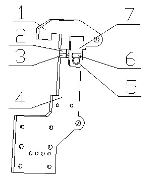
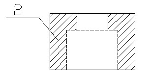
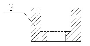
[0014] Such as figure 1 As shown, a body welding jig limit structure, including the compression arm 1, upper limit block 2, lower limit block 3, connecting plate 4, rotating shaft 5, rotating shaft anti-rotation block 6 and hinge plate 7 and other components. The connecting plate 4 is used as a bridge connecting the fixture support and the positioning and pressing unit, its lower end is connected with the fixture support through bolts, and its upper end is connected with the hinge plate 6 and the compression arm 7 through the rotating shaft 5 (the hinge plate 6 and the compression arm 7 Usually carbon dioxide shielded welding is used to connect); in order to prevent the rotation shaft 5 from being severely worn during the movement and resulting in poor connection accuracy and strength, a square rotation shaft anti-rotation block 6 is welded on the hinge plate 7 to be ...


PUM


Abstract

The invention discloses a limiting structure of a vehicle body welding fixture, which comprises a compression arm, an upper stop block, a lower stop block, a connecting plate, a rotary shaft, a rotary shaft rotation-preventive block and a hinge plate. The connecting plate is used for connecting a fixture support with a positioning compression unit, the lower end of the connecting plate is connected with the fixture support by a bolt, the upper end of the connecting plate is connected with the hinge plate and the compression arm, and the hinge plate is connected with the compression arm by means of welding (normally by means of carbon-dioxide arc welding). The limiting structure is characterized in that both the upper stop block and the lower stop block are cylinders, a stepped hole used for assembling a bolt is arranged in the middle of each cylinder, and the upper stop block and the lower stop block are respectively connected with the compression arm and the connecting plate by the countersunk bolts. The limiting structure of the fixture can meet the limiting requirement of the fixture, structural design, processing and manufacture can be simplified, and cost is saved.

Description

technical field [0001] The invention belongs to the field of welding process tooling for a vehicle body welding production line, and in particular relates to a clamp limiting structure. Background technique [0002] In the body welding production process of automobile OEMs, the positioning or pressing part of the welding fixture on the welding production line mostly adopts the guide limit block structure, so as to accurately locate the positioning surface or pressing surface (positioning surface) that requires high position accuracy Generally speaking, for a rotary compression mechanism with more than two stages, the present invention is mainly aimed at the limiting structure of the executive part of the clamping block), this type of guide limiting block is mainly used for one or more of the following situations at the same time Under the circumstances: when the positioning pin is connected to the pressing block, when the pressing force of the lateral movement is large, when...

Claims


Application Information

Patent Timeline
Patent Type & Authority Applications(China)
IPC IPC(8): B23K37/053
Inventor 马志飞冉启洪刘同涛许德林黄勇
Owner CHONGQING CHANGAN AUTOMOBILE CO LTD
Learn More