Rigid frame continuous beam of portal pier

A rigid frame and portal technology, applied in bridges, bridge parts, bridge construction, etc., can solve problems such as cover beams intruding into railway boundaries, reducing the vertical space between the bottom of cover beams and existing railway boundaries, and endangering the safety of railway traffic, etc. , to achieve the effect of reducing the amount of concrete and steel bars, ensuring the railway limit requirements, and reducing the cost of the project

Inactive Publication Date: 2011-12-28
中铁十局集团有限公司
View PDF5 Cites 3 Cited by
  • Summary
  • Abstract
  • Description
  • Claims
  • Application Information

AI Technical Summary

Problems solved by technology

[0003] For the rigid frame continuous beam spanning the existing railway, if the portal pier cover beam is used as the fulcrum of the longitudinal beam, and then the rigid frame continuous beam is constructed on the portal pier cover beam, when the elevation of the top of the longitudinal beam is li

Method used


Image

  • Rigid frame continuous beam of portal pier
  • Rigid frame continuous beam of portal pier
  • Rigid frame continuous beam of portal pier

Examples


Embodiment Construction

[0014] The present invention will be further described below in conjunction with accompanying drawing and non-limiting embodiment:

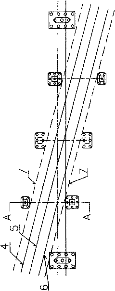
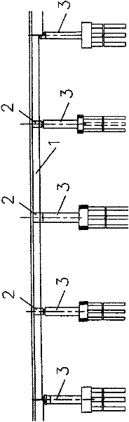
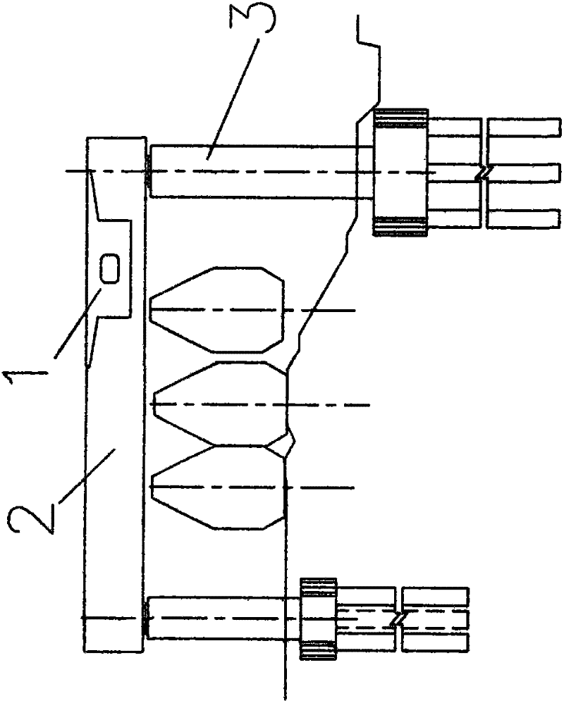
[0015] As shown in the attached figure, it is a rigid frame continuous girder spanning the existing railway line. Its longitudinal direction is rigid frame continuous beam 1, and its lower support structure adopts portal pier 3, and the upper part of portal pier 3 is horizontally arranged. Portal pier cap beam 2. At the junction of the continuous rigid frame beam 1 and the portal pier cover beam 2, the continuous rigid frame beam 1 is embedded in the portal pier cover beam 2, and the continuous rigid frame beam 1 and the portal pier cover beam 2 are integrated by pouring concrete , the upper surface of the rigid continuous beam 1 is flush with the upper surface of the portal pier cap beam or the upper surface of the rigid continuous beam is higher than the upper surface of the portal pier cap beam.

[0016] The other parts of this embodiment ado...


PUM


Abstract

The invention discloses a continuous girder with rigid structure of a portal pier, which belongs to the technical field of bridges. It comprises a rigid frame continuous beam (1) and a portal pier cap beam (2) arranged at the lower part of the rigid frame continuous beam (1), and is characterized in that: At the junction of (2), the rigid frame continuous beam (1) is embedded in the portal pier cap beam (2). The invention can reduce the vertical space occupied by the cover beam and the continuous rigid structure, ensure the limit requirement of the railway, ensure the safety of driving, reduce the consumption of concrete and steel bars, and save the cost.

Description

technical field [0001] The invention relates to a novel bridge structure, in particular to a bridge spanning an existing railway line, and belongs to the technical field of bridges. Background technique [0002] The continuous rigid frame bridge is one of the prestressed concrete continuous girder bridges, generally using variable cross-section box girders. my country's highway system began to design and build continuous rigid frame bridges in the middle of the 1980s, and it has a history of more than 20 years. The continuous rigid frame can be connected with multiple spans, or the side spans can be loosened and supports are used to form a rigid frame-continuous beam system. The joint is seamless, which improves the driving conditions; the beams and piers are consolidated without supports; the rational selection of the stiffness of the beams and piers can reduce the bending moment at the mid-span of the beams, thereby reducing the building height of the beams. Therefore, t...

Claims


Application Information

Patent Timeline
IPC IPC(8): E01D19/00
Inventor 杨基好宋呈超踪高峰张在远张千成桂婞
Owner 中铁十局集团有限公司
Why Eureka
Try Eureka