Shaping clamping fixture for motor coil

A mold and wire bag technology, which is applied in the field of combined elastic motor wire bag shaping mold, can solve the problems of easy damage, affecting product quality, wire bag inner cavity size, shape can not meet the predetermined requirements, etc., to ensure product quality , to prevent the effect of extrusion

Inactive Publication Date: 2012-07-18
TIANJIN YONGHENG MOTOR FACTORY
View PDF5 Cites 1 Cited by
  • Summary
  • Abstract
  • Description
  • Claims
  • Application Information

AI Technical Summary

Problems solved by technology

The disadvantage of the existing inner cavity shaping mold is that the pressure plate and the inverted conical expansion core are integral structures, and the stress is concentrated. When the pressure plate is pressed down, the pressure is greater than the lateral expansion force, which makes the wire squeeze down and is easy to be damaged, and the inner cavity of the wire package The size and shape of the product cannot meet the predetermined requirements, which will affect the product quality

Method used


Image

  • Shaping clamping fixture for motor coil
  • Shaping clamping fixture for motor coil
  • Shaping clamping fixture for motor coil

Examples


Embodiment Construction

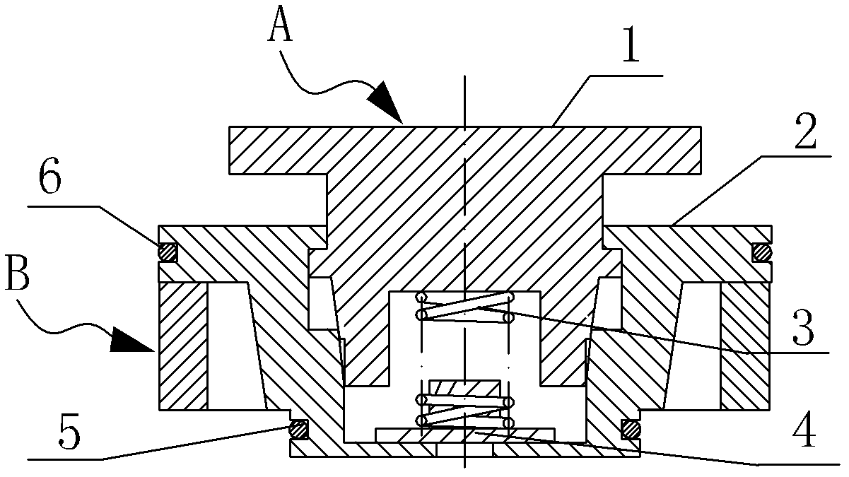
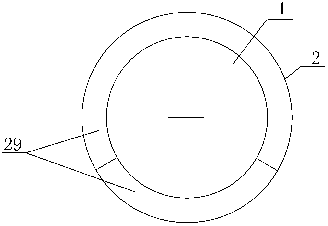
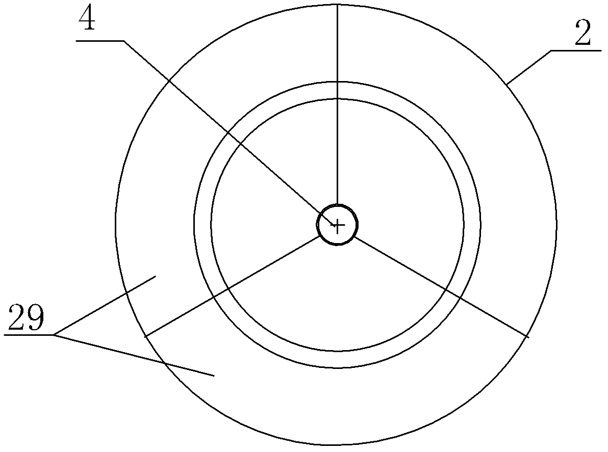
[0018] Figure 1 to Figure 6 It shows a motor wire package shaping mold, Figure 7 is its application diagram. As shown in the figure, the motor wire package shaping tool includes an external shaping tool B and an inner cavity shaping tool A. A is an expansion pressure body for expanding and pressing the inner cavity and the top surface of the end of the wire package of the above-mentioned motor. Elastic ring composition. The above-mentioned expansion sleeve 2 is composed of a top pressure plate 28 part coaxially provided with an expansion core via hole 21 in the center, a middle inverted conical sleeve body 27 part and a bottom cylindrical positioning ferrule 26 part. The expansion core 1 and The expansion sleeve 2 is arranged coaxially, and its top is the force-applying pressure plate 11 above the above-mentioned force-bearing pressure plate 28, and the expansion core body at the lower part of the force-applying pressure plate can move up and down through the above-mentio...


PUM


Abstract

The invention relates to a shaping clamping fixture for a motor coil. The shaping clamping fixture comprises an outer shaping clamping fixture and an inner cavity shaping clamping fixture, wherein the outer shaping clamping fixture is a tension band; and the inner cavity shaping clamping fixture is a swelling pressure body for swelling and pressing the inner cavity and top surface of the end part of the motor coil. The shaping clamping fixture is characterized in that: the inner cavity shaping clamping fixture for the coil mainly comprises a swelling sleeve, a swelling core, a spring and an elastic ring, wherein the swelling sleeve consists of a top stressed pressure plate part, a middle inverted conical sleeve body part and a bottom cylindrical positioning mortise part, which are coaxially arranged; a swelling core through hole is reserved in the center of the top stressed pressure plate part; a force application pressure plate is arranged on the top of the swelling core, and is positioned above the stressed pressure plate; a swelling core body on the lower part of the force application pressure plate is embedded into an inner cavity of the swelling sleeve through the swelling core through hole, and can move up and down; the spring is fixed between the swelling core and the swelling sleeve; the swelling sleeve is formed by splicing more than three same swelling sleeve blocks which are cut by a vertical plane passing through a central axis, and is banded to form a whole through the elastic ring; and the tension band is positioned below the stressed pressure plate. The shaping clamping fixture has the advantages that: damage to a conducting wire is avoided, and coil shaping is ensured to meet set requirements.

Description

technical field [0001] The invention relates to a process device, in particular to a combined elastic motor wire bag shaping mold. Background technique [0002] In the process of motor production and assembly, the wire package wound on the stator must be reshaped after assembly. The traditional shaping mold includes an external shaping mold and an inner cavity shaping mold. The external shaping mold is set outside the end of the wire package. The hoop, whose height is the set height of the end of the wire bag, is used for external shaping and height adjustment of the end of the wire bag; The pressure plate on the top surface of the end of the crimping package and the lower part are provided with an expansion and pressure body of an inverted tapered expansion core inserted into the inner cavity of the crimping package. When in use, put the external shaping tool on the outside of the end of the stator wire package, insert the inverted tapered expansion core of the inner cavit...

Claims


Application Information

Patent Timeline
Patent Type & Authority Applications(China)
IPC IPC(8): H02K15/08
Inventor 李宗和
Owner TIANJIN YONGHENG MOTOR FACTORY
Why Eureka
Try Eureka