Mining elevator lapping platform suitable for flexible guide rail and mining elevator lapping method

A flexible guide rail and platform technology, which is applied to elevators in buildings, lifting equipment in mines, elevators, etc., can solve the problem of unsuitable intermediate multi-level working face overlapping, unsuitable mine elevator overlapping, inclined or partial Protrusions and other problems, to achieve the effect of facilitating the entry and exit of goods and personnel in and out of the elevator, reducing initial investment costs, and convenient installation and maintenance

Active Publication Date: 2012-07-25
CHINA UNIV OF MINING & TECH +1
View PDF8 Cites 11 Cited by
  • Summary
  • Abstract
  • Description
  • Claims
  • Application Information

AI Technical Summary

Problems solved by technology

At present, most elevators use rigid guide rails with a small gap with the car, so there is no platform between the shaft and the well. However, the harsh environment of the mine underground can easily cause the guide rails to tilt, deform, tilt or partially bulge, resulting in the elevator car jamming, etc. potential danger
Although the existing mine hoist system uses the jointing device and cradle between the cage and the hoistway, all of them are installed at the mouth of the hoistway, and each horizontal plane must be equipped with a set of equipment, which is not suitable for the overlapping of multiple horizontal working faces in the middle. not suitable for lapping of mining elevators
At present, there is no lapping platform suitable for flexible guide rails used in mining elevators.

Method used


Image

  • Mining elevator lapping platform suitable for flexible guide rail and mining elevator lapping method
  • Mining elevator lapping platform suitable for flexible guide rail and mining elevator lapping method
  • Mining elevator lapping platform suitable for flexible guide rail and mining elevator lapping method

Examples


Embodiment Construction

[0017] Below in conjunction with accompanying drawing, one embodiment of the present invention is further described:

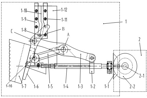
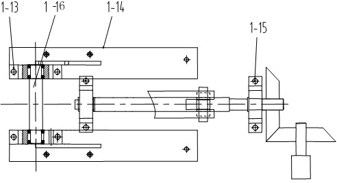
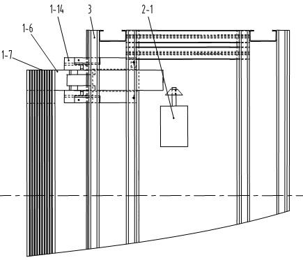
[0018] like Figure 1~3 As shown in the figure, the present invention is suitable for a mining elevator lap platform with flexible guide rails, and is mainly composed of a claw group 1 and a power group 2. The claw group 1 and the power group 2 pass through the explosion-proof motor 2-1 shaft of the power group 2. The driving bevel gear 2-2 and the driven bevel gear 1-1 on the lead screw 1-4 of the push claw group 1 mesh with each other for transmission; the claw group 1 includes two installations symmetrically arranged on the cross beam 3 at the bottom of the car Plate 1-14, the left side between the two mounting plates 1-14 is provided with a supporting rod shaft 1-16 fixed by the mounting seat 1-13, and the middle of the two mounting plates 1-14 is provided with the supporting rod shaft 1-16 The lead screw bearing seat 1-15 with the vertical space position...


PUM


Abstract

The invention discloses a mining elevator lapping platform suitable for a flexible guide rail and a mining elevator lapping method. The lapping platform mainly comprises a power pack and a support claw pack, wherein the power pack comprises an explosion-proof motor and a bevel gear; the support claw pack comprises a mounting plate, a support, a screw rod, a screw nut, a support rod, a connecting rod, a support claw, a guide rail and a guide rail frame; and the support claw pack and the power pack are all installed on a cross beam below an elevator car. The lapping method is as follows: the sharing between a lapping platform and a plurality of horizontal planes is realized, the self locking function is achieved, the reliable connection of the lapping platform in the plurality of horizontal planes is met, the reliable lapping between the elevator car and a hoistway layer door is realized, and the mining elevator lapping platform plays the role of safety protection, convenience in entrance and exit of the elevator for cargos and people. The mining elevator lapping platform has a simple structure, is accurate in control, convenient to install and maintain, stable in running and improves the safety and reliability of moving the load in and out of the elevator car.

Description

technical field [0001] The invention relates to an elevator lap joint platform and a lap joint method, in particular to a mine elevator lap joint platform and a lap joint method suitable for flexible guide rails. technical background [0002] With the centralized and large-scale development of mine production, mine elevators are used as a means of transportation for lifting personnel and materials between multiple levels of mine shafts (blind shafts). At present, most elevators use rigid guide rails with a small gap with the car, so there is no building platform between them and the hoistway. However, the harsh environment in the mine can easily lead to the guide rail being inclined, deformed, inclined or partially protruded, resulting in elevator car rails, etc. Potentially dangerous. The existing mine hoist system, although using the supporting device and the shaking table between the cage and the shaft, are all installed at the shaft mouth, and each horizontal plane mus...

Claims


Application Information

Patent Timeline
IPC IPC(8): B66B17/00B66B5/00
CPCB66B17/00B66B17/24B66B17/16B66B13/301B66B17/18
Inventor 朱真才曹国华秦健聪康虹桥李伟周公博陈国安吴仁愿马依萍杨建荣
Owner CHINA UNIV OF MINING & TECH
Why Eureka
Try Eureka