

Quick heating type heat pump water heater for recovering shower waste heat
A heat pump water heater and regenerator technology, applied in heat pumps, fluid heaters, heat recovery systems, etc., can solve the problems of frequent start and stop of compressors, no heat source, etc., and achieve reasonable power input distribution control, heat source temperature stability, power and high efficiency
- Summary
- Abstract
- Description
- Claims
- Application Information
AI Technical Summary
Problems solved by technology
Method used
Image


Examples
Embodiment Construction
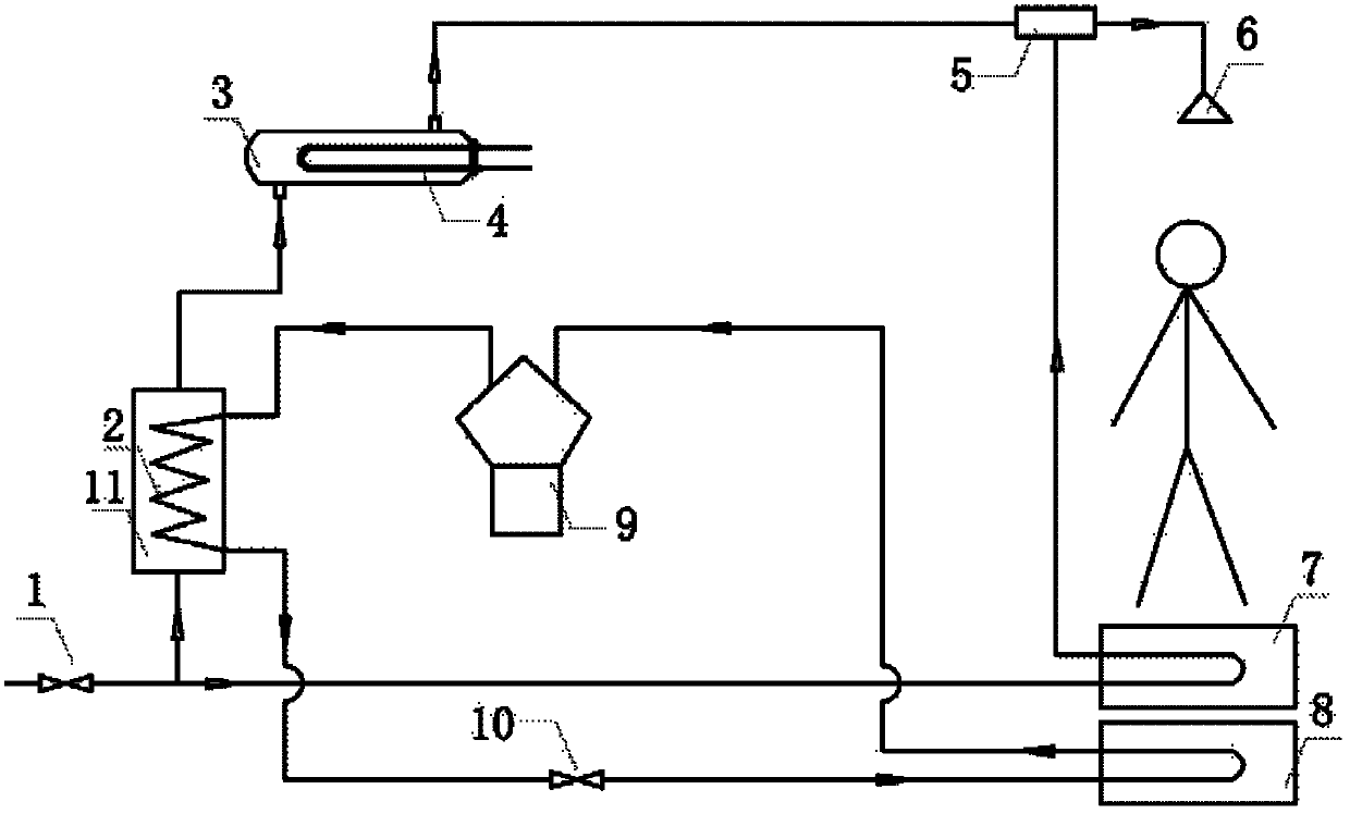
[0048] like figure 1 As shown, the heat pump water heater consists of the following parts: valve 1, condenser 2, auxiliary water tank 3, preheater 4, water mixing controller 5, spray device 6, regenerator 7, evaporator 8, compressor 9. Throttling device 10, main water tank 11. The position connection relationship between them is: the regenerator 7 and the evaporator 8 are installed under the feet of the shower person, the regenerator 7 is on the top, and the evaporator 8 is on the bottom; One end communicates with the mixing water controller 5; the preheater 4 is placed in the auxiliary water tank 3, the condenser 2 is placed in the main water tank 11, the water outlet of the auxiliary water tank 3 is connected with the inlet of the mixing water controller 5, and the auxiliary water tank 3 enters water One end of the valve 1 is connected to the tap water, and the other end is connected to the water inlet pipe of the main water tank 11 and the water inlet pipe of the regenera...
PUM
 Abstract
Description
Claims
Application Information