Photographing optical lens assembly

An optical lens and lens technology, applied in optics, optical components, instruments, etc., can solve the problems of large field of view and difficulty in shortening the total length of the optical lens group, and achieve the effects of improving brightness, improving resolution, and increasing efficiency

Active Publication Date: 2012-07-25
LARGAN PRECISION
View PDF13 Cites 11 Cited by
  • Summary
  • Abstract
  • Description
  • Claims
  • Application Information

AI Technical Summary

Problems solved by technology

Wide-angle fixed focal length optical lenses have many different designs. In the three-element wide-angle small optical lens group, the known technology combines different positive or negative refractive powers, such as US Patent Publication Nos. US2009 / 080089, US2010 / 157443, and US2010 / 231686, US7,301,808, etc., mainly adopt the combination design of positive refractive power, negative refractive power and positive refractive power, but in order to achieve high imaging quality, the overall length of the optical lens group is difficult to shorten
US Patent Publication No. US2006171042 adopts a combination design of negative refractive power, positive refractive power and positive refractive power, but its field angle is relatively large, and the overall length of the optical lens group is difficult to shorten

Method used


Image

  • Photographing optical lens assembly
  • Photographing optical lens assembly
  • Photographing optical lens assembly

Examples


no. 1 example

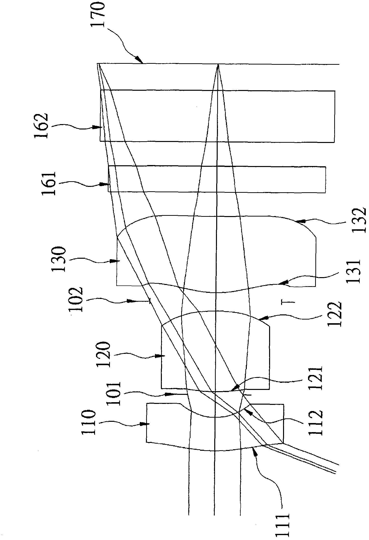
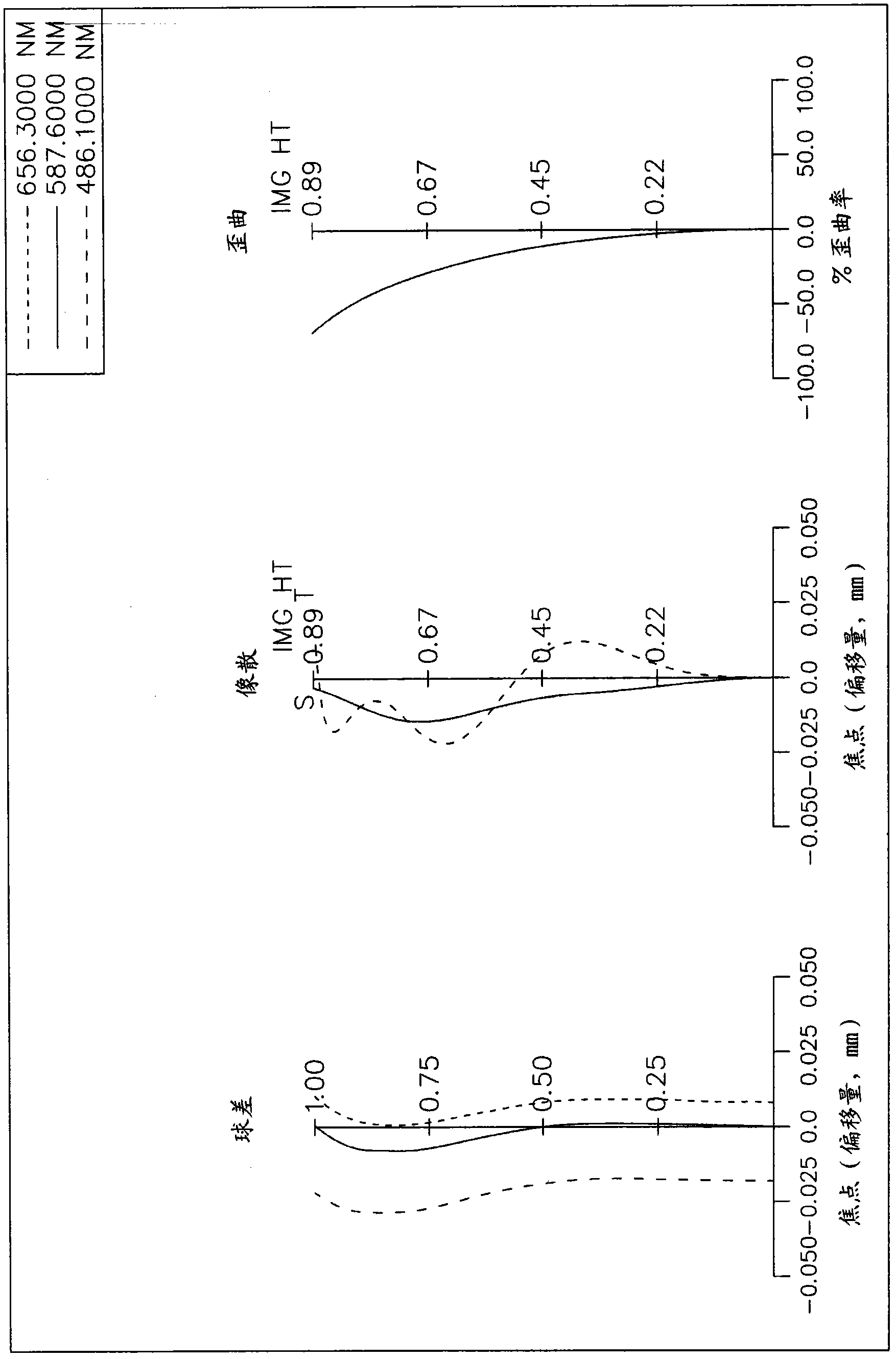
[0106] Please refer to the schematic diagram of the optical system of the first embodiment of the present invention Figure 1A , for the aberration curve of the first embodiment, please refer to Figure 1B . The imaging optical lens group of the first embodiment is an optical lens group mainly composed of three lenses, aperture 101, aperture stop 102, infrared filter filter 161 and protective glass 162; The side to the image side includes in sequence: a first lens 110 with negative refractive power. In this embodiment, the first lens 110 is a lens made of plastic material, its object-side optical surface 111 is a convex surface, and its image-side optical surface 112 is a concave surface. , its object side optical surface 111 and image side optical surface 112 are both aspherical surfaces; aperture 101; the second lens 120 with positive refractive power is a lens made of plastic material, its object side optical surface 121 is a convex surface, and its image side The optical ...

no. 2 example

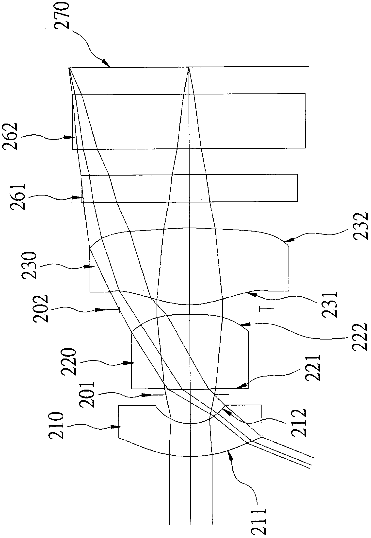
[0114] Please refer to the schematic diagram of the optical system of the second embodiment of the present invention Figure 2A , for the aberration curve of the second embodiment, please refer to Figure 2B . The imaging optical lens group of the second embodiment is mainly composed of three lenses, an aperture 201, an aperture stop 202, an infrared filter filter 261, and a protective glass 262; To the image side, it includes: a first lens 210 with negative refractive power. In this embodiment, the first lens 210 is a lens made of plastic material, its object-side optical surface 211 is a convex surface, and its image-side optical surface 212 is a concave surface. Its object side optical surface 211 and image side optical surface 212 are all aspheric surfaces; Aperture 201; The second lens 220 with positive refractive power is a lens made of plastic material, its object side optical surface 221 is a convex surface, and its image side optical surface The surface 222 is a con...

no. 3 example

[0122] Please refer to the schematic diagram of the optical system of the third embodiment of the present invention Figure 3A , for the aberration curve of the third embodiment, please refer to Figure 3B . The imaging optical lens group of the third embodiment is an optical lens group mainly composed of three lenses, aperture 301, aperture stop 302, infrared filter filter 361 and protective glass 362; The side to the image side includes: a first lens 310 with negative refractive power. In this embodiment, the first lens 310 is a lens made of plastic material, and its object-side optical surface 311 is a convex surface, and its image-side optical surface 312 is a concave surface. , its object-side optical surface 311 and image-side optical surface 312 are all aspheric surfaces; aperture 301; the second lens 320 with positive refractive power is a lens made of plastic material, its object-side optical surface 321 is a convex surface, and its image-side optical surface The op...


PUM


Abstract

A photographing optical lens assembly, sequentially arranged from an object side to an image side, comprising: the first lens element with negative refractive power having a convex object-side surface and a concave image-side surface, the second lens element with positive refractive power having bi-convex surfaces, the third lens element with positive refractive power having a convex object-side surface, at least one aspherical surface and at least one inflection point on at least one optical surface. Additionally, the photographing optical lens assembly comprises a stop and satisfies condition such as 0.75<SL / TTL<1.1, wherein SL is the axial distance from the stop to the image plane, TTL is the axial distance from the object-side surface of first lens element to the image plane. By such arrangements, the photographing optical assembly can effectively correct the aberration and obtain superior image quality.

Description

technical field [0001] The invention relates to an optical lens group for photographing, in particular to an optical lens group composed of three lenses with a wide-area viewing angle for application in electronic products. Background technique [0002] Optical lens groups are often installed on small electronic devices such as digital cameras (Digital Still Cameras) and mobile phone cameras (Mobile Phone Cameras) to take pictures of objects. , but at the same time, it is also hoped to achieve an optical lens group with good aberration correction capability, high resolution and high imaging quality. [0003] In the optical lens group of small electronic products, there are known different designs of two-lens type, three-lens type, four-lens type and five-lens type. Function MTF (Modulation Transfer Function) has more advantages in performance, but its cost is higher, and the two-element optical lens group is difficult to meet the high-resolution requirements; therefore, the...

Claims


Application Information

Patent Timeline
Patent Type & Authority Applications(China)
IPC IPC(8): G02B13/06G02B13/18G02B13/00G02B13/22G02B1/04
CPCG02B13/04G02B13/0035
Inventor 许伯纶周明达
Owner LARGAN PRECISION
Why Eureka
Try Eureka