Control method and device for air-sucking/blowing of structure around flow field

A technology of air blowing control and circumvention, which is applied in the flow control of auxiliary non-electric power, etc., can solve the problems of huge energy, high price, difficult maintenance, etc., achieve a wide range of applications, precise and fast control, and improve wind-induced stability Effect

Inactive Publication Date: 2012-07-25
欧进萍 +2
View PDF5 Cites 7 Cited by
  • Summary
  • Abstract
  • Description
  • Claims
  • Application Information

AI Technical Summary

Problems solved by technology

However, increasing the overall stiffness of the structure and increasing the structural damping will require huge energy, difficult maintenance, and expensive, and introducing various measures to change the aerodynamic force acting on the structural section will produce a good aerodynamic effect

Method used


Image

  • Control method and device for air-sucking/blowing of structure around flow field
  • Control method and device for air-sucking/blowing of structure around flow field
  • Control method and device for air-sucking/blowing of structure around flow field

Examples


Embodiment 1

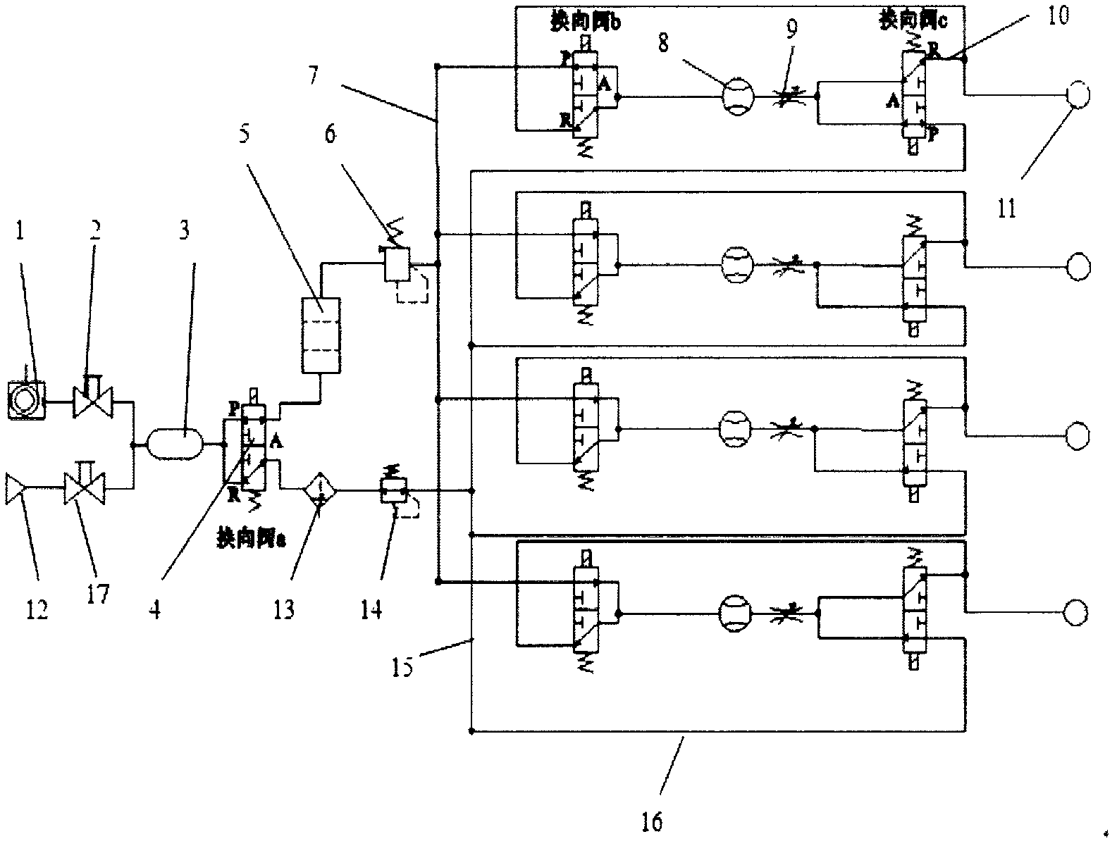
[0017] Example 1: Combining figure 1 , the present invention is a structure around the flow field suction / blowing control device, which is composed of a vacuum pump (1), A ball valve (2), air pump (12), B ball valve (17), gas storage tank (3), electromagnetic converter Directional valve (4), vacuum filter (5), ordinary filter (13), precision pressure reducing valve (14), vacuum pressure reducing valve (6), blowing air main pipe (15), suction air main pipe (7), suction branch pipe (10), suction / blowing port (11), flow meter (8), throttle valve (9), blowing air flow main pipe (15) and blowing branch pipe (16) , the vacuum pump (1) is connected to ball valve A (2), the air pump (12) is connected to ball valve B (17), and the air storage tank (3) is connected to ball valve A (2), ball valve B (17) and electromagnetic reversing valve (4) respectively , the electromagnetic reversing valve (4) is respectively connected to the vacuum filter (5) and the ordinary filter (13), the vacuu...

Embodiment 2

[0023] Example 2: Combining figure 1 , The air suction / blowing control method around the flow field of the structure described in the present invention is a new technology for actively controlling the air flow of the structure section through external energy supply, thereby improving the aerodynamic characteristics of the structure. The invention is realized by a structure surrounding the air suction / blowing control device of the flow field. Utilize miniature sensors to monitor the flow characteristics and wind speed around the structural section in real time, and the feedback system will issue instructions after analyzing and processing the measured information to control the opening or closing of the power device of the suction / blowing control device around the flow field of the structure, and at the same time adjust various control devices The amount of energy provided by the power plant. The airflow port of the suction / blowing control device around the flow field of the s...

Embodiment 3

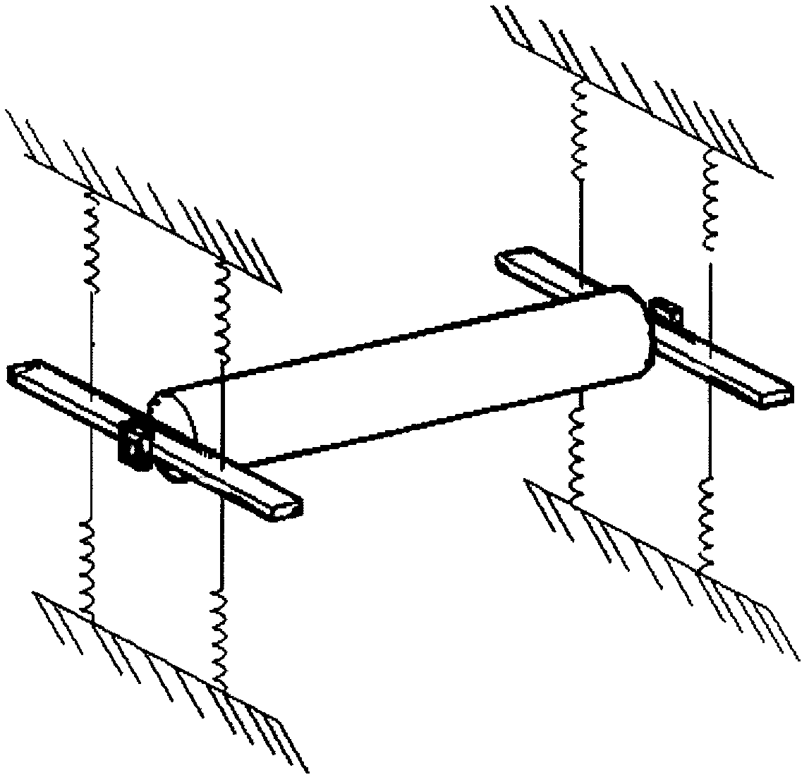
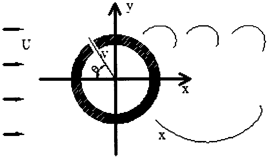
[0027] Example 3: Binding figure 2 , image 3 , Figure 4 , Figure 5 , using the suction / blowing control method around the structure to complete the vortex-induced vibration control experiment of the cable structure. The structure of the cable on the free vibration device is as follows figure 2 shown. image 3 is the cross section of the cable, in the figure, the angle between the suction hole and the horizontal axis is θ, and the wind speed of the front end of the cable is U. Through pre-design, given the position of the suction hole as θ=135°, the relationship between the preset incoming wind speed and the flow speed of the suction / blowing device is as follows: Figure 4 shown. Figure 4 Among them, the abscissa is the incoming wind speed, and the ordinate is the mean square error of the vibration acceleration of the cable structure, U q is the flow rate of the blowing / suction device, from Figure 4 It can be seen from the figure that the minimum value of the pres...


PUM


Abstract

The invention provides a control method and device for air-sucking / blowing of a structure around a flow field. The device comprises a vacuum pump, an air pump, an air storage tank, an electromagnetic reversing valve, a vacuum filter, a precise pressure-reducing valve, a vacuum pressure-reducing valve, an air-blowing / sucking airflow main pipeline, a flow meter and a throttle valve, wherein the air storage tank is respectively connected with a ball valve A, a ball valve B and the electromagnetic reversing valve; the electromagnetic reversing valve is respectively connected with the vacuum filter and a common filter; the vacuum filter is connected with the vacuum pressure-reducing valve; and the vacuum pressure-reducing valve is connected with the air-blowing / sucking airflow main pipeline. In the invention, an action effect of an air-blowing / sucking airflow control structure under a natural incoming flow air field is utilized to design and arrange an air-sucking / blowing device in advance, a relation of the air speed of the incoming flow and the flow of the air-sucking / blowing device is designed and preset, and the flow of the air-sucking / blowing device is controlled by comparing the monitored air speed of the incoming flow with the preset air speed of the incoming flow. The device provided by the invention is capable of improving a wind-induced feature of the structure and increasing the wind-induced stability of the structure and is used for wind tunnel test research for various models, such as super high-rise buildings, large span bridges, oceanographic engineering structures, and the like.

Description

technical field [0001] The invention relates to an engineering structure aerodynamic testing method, specifically a method and device for controlling the suction / blowing of a structure around a flow field Background technique [0002] Under the action of wind, engineering structures may experience static aerodynamic instability, flutter, galloping, buffeting and vortex-induced vibration, among which flutter and galloping will cause devastating damage to the structure, buffeting will lead to local fatigue of the structure, vortex-induced Vibration can easily cause fatigue damage to the structure. With the development of lightweight and high-strength materials and the enhancement of structural calculation capabilities, engineering structures are developing towards large-span, lightweight and flexible trends. At the same time, structural stiffness and damping are reduced, and the sensitivity to wind loads is gradually increasing. , wind load and wind-induced stability have bec...

Claims


Application Information

Patent Timeline
IPC IPC(8): G05D7/03
Inventor 欧进萍辛大波李惠张明晶段忠东
Owner 欧进萍
Why Eureka
Try Eureka