

Integrated transformer
A technology of transformers and voltage transformers, which is applied in the direction of inductors, transformers, high-voltage air circuit breakers, etc., can solve the problems of cumbersome wiring, large volume, and expensive installation costs, and achieve the effect of beautiful appearance and easy installation
Inactive Publication Date: 2012-07-25
JIANGSU TIANCHI ELECTRIC
View PDF0 Cites 2 Cited by
- Summary
- Abstract
- Description
- Claims
- Application Information
AI Technical Summary
Problems solved by technology
The voltage transformer and current transformer are used in conjunction with the vacuum circuit breaker as an external type, which is large in size, cumbersome in wiring, and consumes installation costs
Method used
View moreImage
Smart ImageViewing Examples

Examples
Embodiment Construction
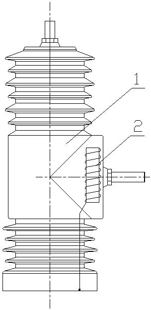
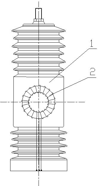
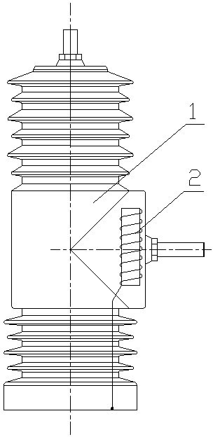
[0008] Such as figure 1 , 2 As shown, the epoxy resin insulating cylinder 1 is formed by pouring epoxy resin, and the voltage transformer and the current transformer 2 are arranged in the epoxy resin insulating cylinder 1, and the voltage transformer and the current transformer are arranged at the lower bottom of the epoxy resin insulating cylinder 1. The signal output terminal of transformer 2.
Login to View More PUM
 Abstract
An integrated transformer relates to the technical field of production of outdoor high-voltage permanent-magnet vacuum circuit breakers. A voltage transformer and a current transformer are arranged in an epoxy resin insulating cylinder, and signal outlet terminals of the voltage transformer and the current transformer are arranged at the bottom of the epoxy resin insulating cylinder. Compared with the conventional integrated transformer, the integrated transformer has the advantages that actual current and voltage values on the primary line can be accurately converted into low secondary current and low secondary voltage which cannot interfere with each other to bring convenience to measurement during running due to the fact that the current transformer and the voltage transformer are hermetically cast in a casting body provided with a vacuum arc-extinguishing chamber. Accordingly, error caused by complicated wiring of mounted integrated transformer during mounting on sites can be avoided on the premise of keeping function constant, the mounting process is simplified and the integrated transformer is more attractive in appearance.
Description
technical field [0001] The invention relates to the technical field of outdoor high-voltage permanent magnet vacuum circuit breaker production. Background technique [0002] The current transformers used in medium-voltage vacuum circuit breakers include voltage transformers and current transformers, which are independent of each other. The voltage transformer and current transformer are used in conjunction with the vacuum circuit breaker as an external type, which is large in size, cumbersome in wiring, and consumes installation costs. Contents of the invention [0003] The purpose of the invention is to propose a comprehensive transformer which is convenient to install. [0004] In the present invention, a voltage transformer and a current transformer are arranged in the epoxy resin insulating cylinder, and the signal connection terminals of the voltage transformer and the current transformer are arranged at the lower bottom of the epoxy resin insulating cylinder. [00...
Claims
Login to View More Application Information
Patent Timeline
 Patent Type & AuthorityApplications(China)
IPC IPC(8): H01F38/34H01H33/66
Inventor邹迅赵爱峰
OwnerJIANGSU TIANCHI ELECTRIC