Radiological image equipment and automatic following method thereof

A technology of automatic follow-up and imaging equipment, which is applied in the fields of radiological diagnostic equipment, medical science, and diagnosis. Achieve good shooting effect and flexible use

Active Publication Date: 2012-08-01
SHENZHEN MINDRAY BIO MEDICAL ELECTRONICS CO LTD
View PDF3 Cites 7 Cited by
  • Summary
  • Abstract
  • Description
  • Claims
  • Application Information

AI Technical Summary

Problems solved by technology

[0005] In the existing scheme, when the angle of the detector or the angle of the nose changes, the alignment of the nose and the detector cannot be guaranteed, which is inconvenient for certain requirements to shoot in a straight position
For example, when the patient's foot needs to be photographed, the angle of the detector will be adjusted to facilitate the patient's foot placement, and the existing solutions cannot meet the requirements of orthographic photography

Method used


Image

  • Radiological image equipment and automatic following method thereof
  • Radiological image equipment and automatic following method thereof
  • Radiological image equipment and automatic following method thereof

Examples


Embodiment Construction

[0021] Other aspects and advantages of the invention will become apparent upon reading the following description and specific embodiments.

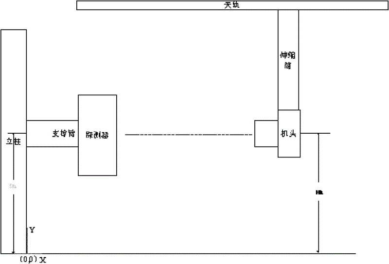
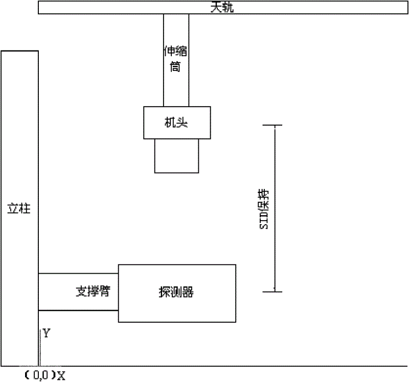
[0022] The "front surface of the detector" mentioned in this article refers to the surface of the detector that receives the incident X-rays.

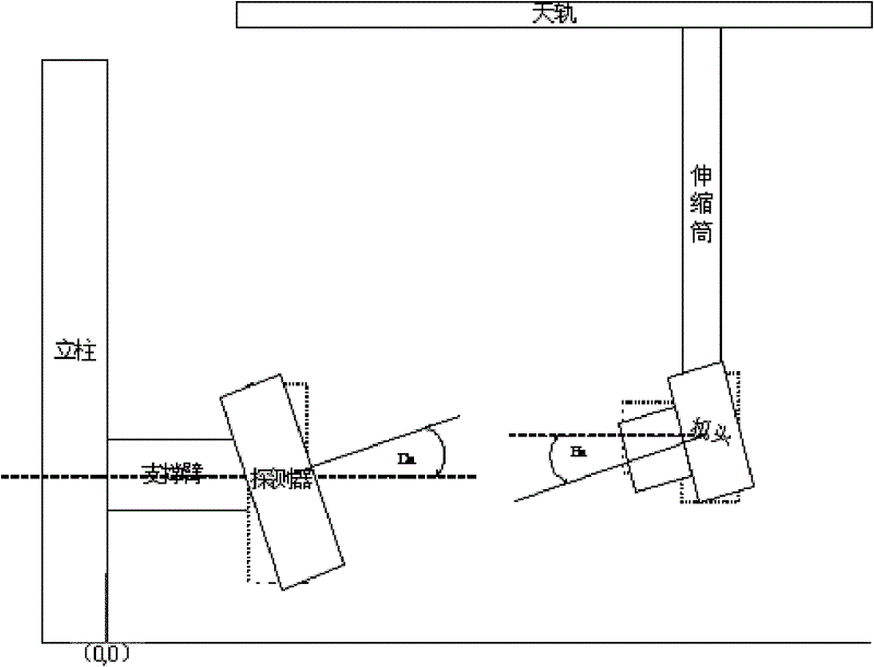
[0023] The "alignment between the detector and the machine head" mentioned in this article means that the angle between the X-rays emitted by the machine head and the front surface of the detector remains unchanged, including that the X-rays are perpendicular to the front surface of the detector and have a fixed angle difference.

[0024] The "detector angle" mentioned in this article refers to the angle value with the horizontal line as the starting edge and the vertical line emitted from the front surface of the detector as the terminal edge; when the front surface of the detector is facing to the right, the angle value is 0; When the front surface of the detector is facing upwards, the value of...


PUM


Abstract

The invention discloses an automatic following method of radiological image equipment. The method comprises the steps of: obtaining a detector angle value; determining a handpiece target angle value corresponding to the detector angle value, wherein the target angle value is equal to the sum of the detector angle value and a preset value; and controlling a handpiece to carry out following motion to achieve the target angle. A synchronous following motion of the handpiece or a detector is realized when the angle of the detector or the handpiece in the radiological image equipment changes, the included angle of the X ray direction and the front surface of the detector is unchanged, and the method guarantees that the radiological image equipment is flexible in application and good in shooting effect.

Description

technical field [0001] The present invention relates to radiographic equipment. More specifically, the present invention relates to a method for automatically following a head and a detector in a cantilever type radiological imaging device. Background technique [0002] In DR photographic inspection, automatic follow-up is a common machine positioning method for DR in the form of a cantilever arm. Current follow-up actions usually take the following forms: [0003] 1. Chest X-ray position tracking: when the height of the detector changes, the height of the machine head also changes; or when the height of the machine head changes, the height of the detector changes accordingly; the relative height difference between the machine head and the detector, namely Dh and Hh The difference between remains constant (see figure 1 ). [0004] 2. Following under the bed: the front surface of the detector is close to the horizontal direction; when the height of the detector changes, t...

Claims


Application Information

Patent Timeline
Patent Type & Authority Applications(China)
IPC IPC(8): A61B6/00
Inventor 刘兵全文琪
Owner SHENZHEN MINDRAY BIO MEDICAL ELECTRONICS CO LTD
Why Eureka
Try Eureka