
Automatic molding machine for cross girder type steel bar

An automatic forming machine and traveling beam technology, which is applied in the field of steel bar bending machines, can solve the problems of high labor intensity, increase of worker's operation steps, and low work efficiency, so as to reduce labor intensity, save operation procedures, improve work efficiency and The effect of construction progress

Active Publication Date: 2014-02-05
冯广建
View PDF8 Cites 0 Cited by
  • Summary
  • Abstract
  • Description
  • Claims
  • Application Information

AI Technical Summary

Problems solved by technology

The steel skeleton frame has five corners. Generally speaking, it is necessary to bend two corners first, then turn around and bend the two corners at the other end, and finally manually bend the last corner in the middle of the steel bar, a total of five times The bending process makes the steel bar bend into a rectangular frame, which is labor-intensive and low-efficiency
[0003] At present, most of the mechanical steel bar bending machines used in the market are generally only composed of a fixed or movable bending mechanism set on the frame. The worker feeds the material again and adjusts the length of the material, which is not only troublesome to operate, but also easily affects the dimensional accuracy of the steel bar
[0004] The invention "a multi-elbow steel bar bending machine" with the publication number CN 10124956A partially solves the above problems, but this device can only process the steel bars that have been bent at both ends, and cannot bend the straight steel bars at one time. , it is necessary to bend the two ends of the straight steel bars on other machines first, and then put them into the device. This requires the use of two different equipment, which virtually increases the number of operating steps for workers.

Method used


Image

  • Automatic molding machine for cross girder type steel bar
  • Automatic molding machine for cross girder type steel bar
  • Automatic molding machine for cross girder type steel bar

Examples


Embodiment Construction

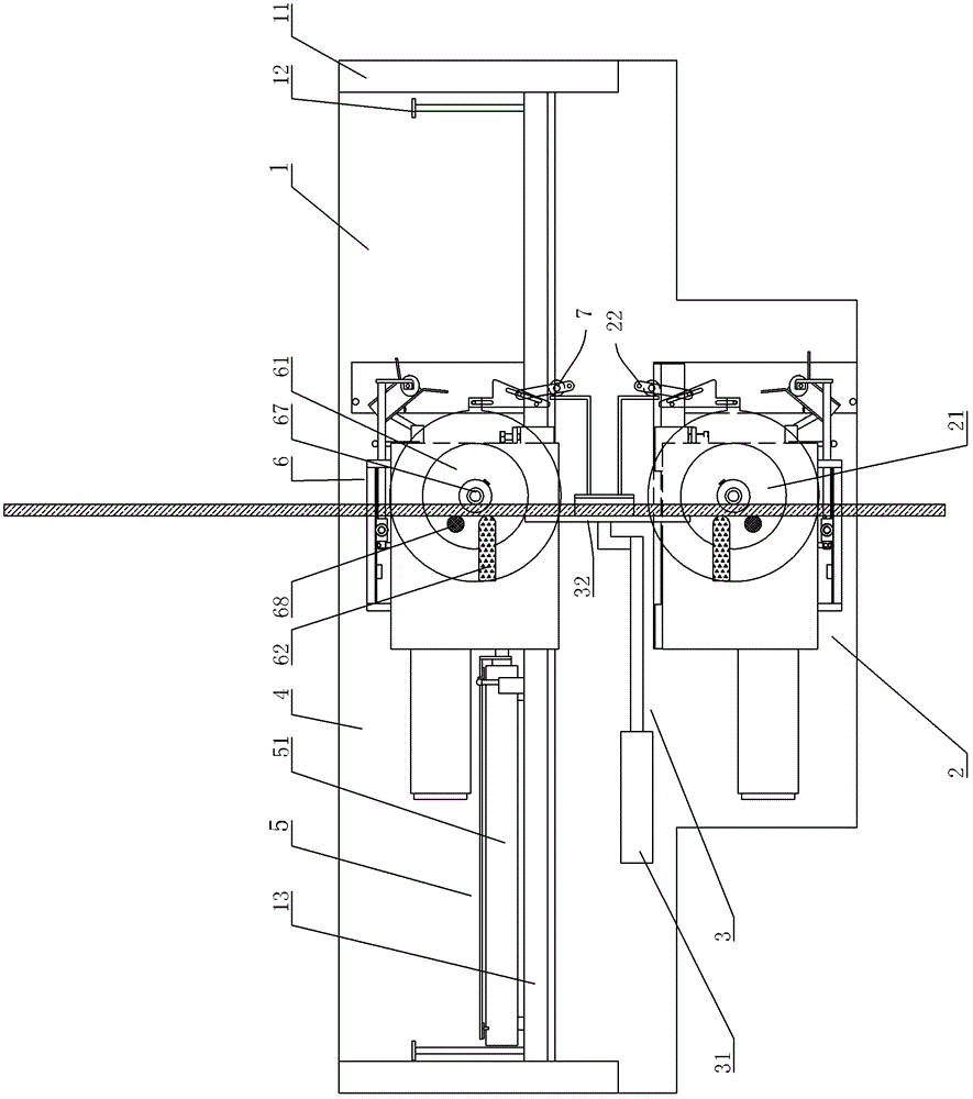
[0034] Such as figure 1 As shown, a running beam type steel bar automatic forming machine includes a frame 1, and guide rails 11 are arranged on both sides of the frame 1, and guide rail beams 13 are fixed between the guide rails 11 through adjusting screw rods 12, and the adjusting screw rods can be adjusted by tightening and loosening 12 to make the guide rail beam 13 move between the two guide rails, thereby adjusting the position of the guide rail beam 13 to adapt to the bending requirements of steel bars of different specifications and models.

[0035] The frame 1 is provided with a fixed bending mechanism 2, a steel bar driving mechanism 3 and a movable bending mechanism 4 from front to back.

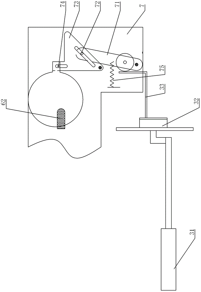
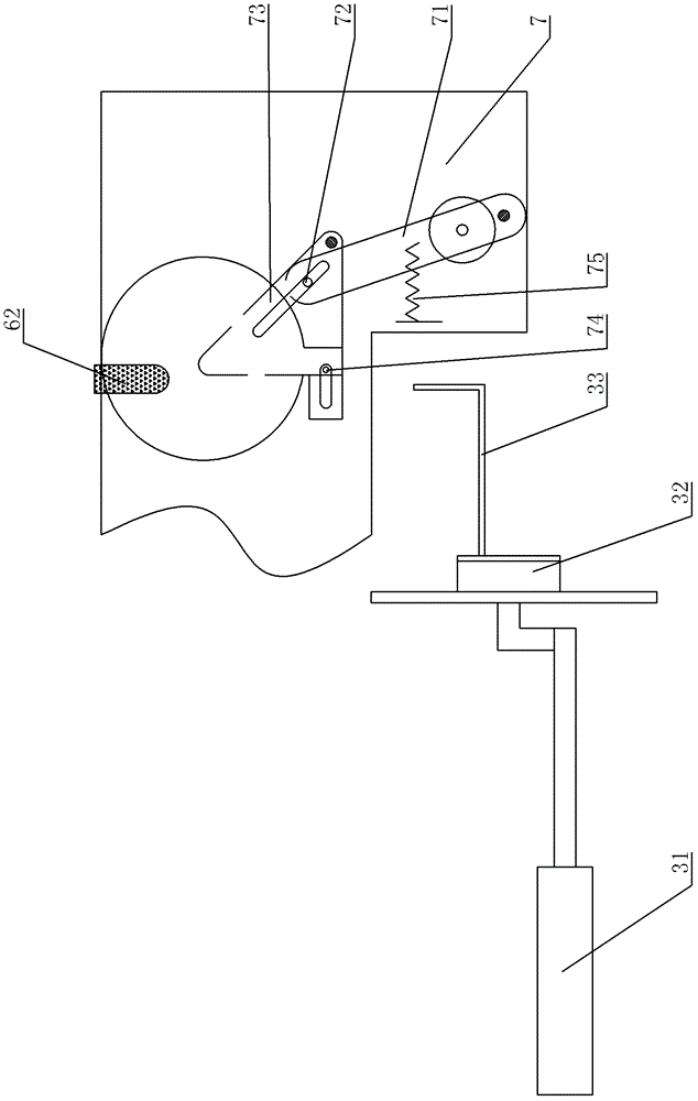
[0036] Such as figure 1 , Figure 4 and Figure 5 As shown, the mobile bending mechanism 4 is composed of two parts, which are a driving device 5 and a bending device 6 respectively. The driving device 5 includes a first oil cylinder 51 fixed on the guide rail beam 13 , a trav...


PUM


Abstract

The invention discloses an automatic molding machine for a cross girder type steel bar, which comprises a frame, wherein guide rails are arranged on two sides of the frame; a guide rail beam is fixed between the guide rails through an adjusting screw rod; the position of the guide rail beam in the guide rails is adjusted by the adjusting screw; and a fixed type bending mechanism, a steel bar driving mechanism for moving the steel bar and a moveable type bending mechanism are arranged on the frame from front to back. After the fixed type bending mechanism, the steel bar driving mechanism and the moveable type bending mechanism are used in a combined form, the steel bar is placed into the automatic molding machine provided by the invention, so that once bending molding of the steel bar is realized and a steel bar framework largely used in a building site is formed. Compared with a traditional steel bar bending machine, the automatic molding machine provided by the invention has the advantages that the operation process is saved, the labor intensity of workers is relieved and the working efficiency and construction progress are greatly increased.

Description

technical field [0001] The invention relates to a steel bar bending machine in the technical field of construction, in particular to a running beam automatic steel bar forming machine. Background technique [0002] In construction engineering, the steel skeleton frame of reinforced concrete usually needs to be bent from steel bars. The steel skeleton frame has five corners. Generally speaking, it is necessary to bend two corners first, then turn around and bend the two corners at the other end, and finally manually bend the last corner in the middle of the steel bar, a total of five times The bending process makes the steel bar bend into a rectangular frame, which has high labor intensity and low work efficiency. [0003] At present, most of the mechanical steel bar bending machines used in the market are generally only composed of a fixed or movable bending mechanism set on the frame. The worker feeds the material again and adjusts the length of the feed, which is not onl...

Claims


Application Information

Patent Timeline
Patent Type & Authority Patents(China)
IPC IPC(8): B21F1/00
Inventor 冯广建
Owner 冯广建
Learn More