Threading silk yarn lifting mechanism used on threading silk yarn spring test equipment

A technology of testing equipment and lifting mechanism, which is applied to auxiliary equipment for weaving, textile, textile and papermaking, etc., can solve the problems of no special equipment for wire springs and long testing time, and achieve the effect of shortening test results.

Inactive Publication Date: 2012-08-01
ZHEJIANG KD TEXTILE MACHINERY
View PDF6 Cites 3 Cited by
  • Summary
  • Abstract
  • Description
  • Claims
  • Application Information

AI Technical Summary

Problems solved by technology

Because the spring is constantly pulled up and back, there are high requirements for the strength of the spring and other indicators. Every time a batch of springs are used, they need to be tested first. Now there is no special equipment for the test of the wire spring. Test by manual means, judged by the experience of technicians, the test time is longer

Method used


Image

  • Threading silk yarn lifting mechanism used on threading silk yarn spring test equipment
  • Threading silk yarn lifting mechanism used on threading silk yarn spring test equipment
  • Threading silk yarn lifting mechanism used on threading silk yarn spring test equipment

Examples


Embodiment Construction

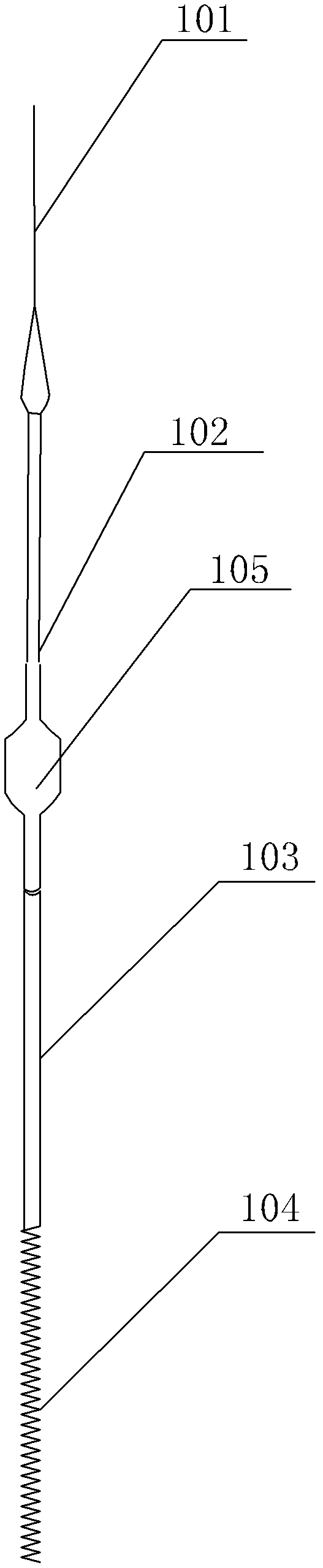
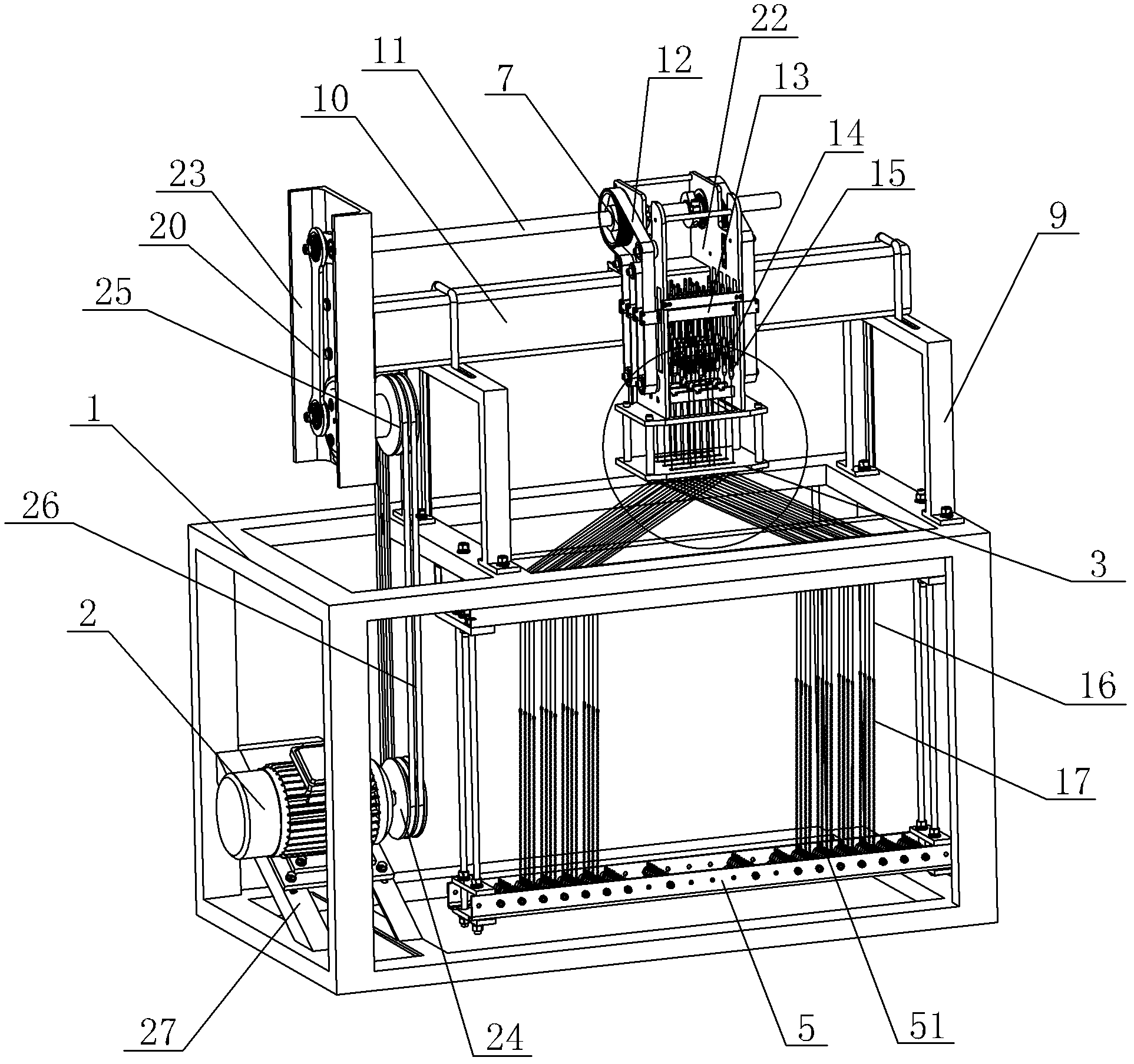
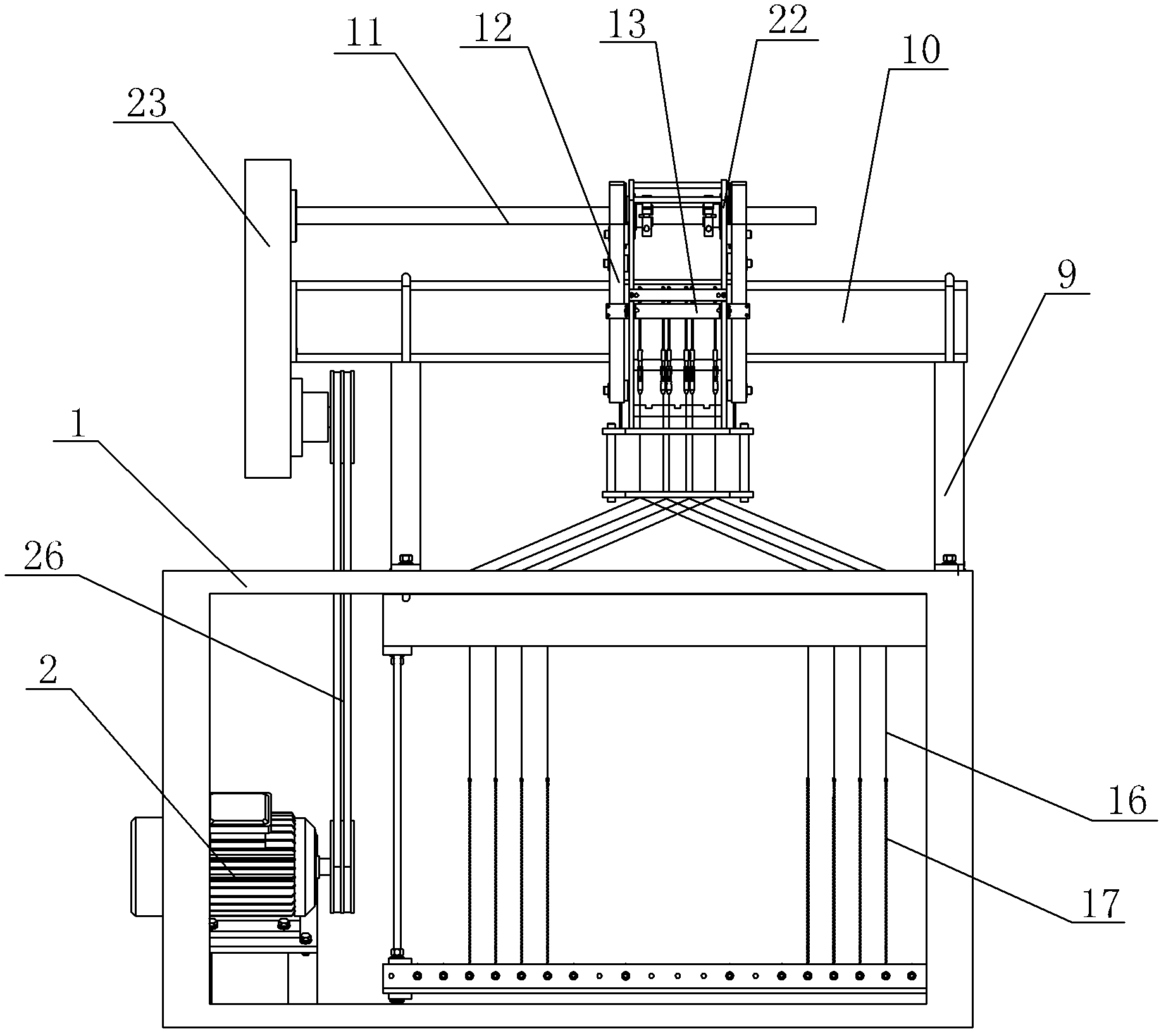
[0017] Such as figure 2 , the wire spring testing equipment of the wire wire lifting mechanism of the present invention is housed, comprising a bed body 1, a motor 2, a return heald frame 5, the output end of the motor 2 is connected to a crank rocker mechanism, and the crank rocker mechanism is connected to a transmission shaft 11, and the transmission The shaft 11 is connected with the thread-through lifting mechanism, the transmission belt 12 of the thread-through lifting mechanism is fixed with a hook clip 13, the hook clip 13 is fixed with a joint hook 14, the joint hook 14 is connected with a quick connector 15, and the quick connector 15 is connected with a thread 16 , the threading thread 16 passes through the threading hole 31 on the threading plate 3 and the eyelet 41 on the frame 4 in turn, the threading thread 16 is connected to the spring 17 below the frame 4 through the heald rod, and the spring 17 is fixed on the heddle Box 5 on.

[0018] Such as image 3 , t...


PUM


Abstract

The invention discloses a threading silk yarn lifting mechanism used on threading silk yarn spring test equipment. The threading silk yarn lifting mechanism comprises a driving belt which is connected with a driving wheel and a plurality of driven wheels, the driving wheel is fixedly connected with a driving shaft, the driven wheels are arranged up and down respectively, the driving belt is divided into a plurality of sections which are arranged in parallel, and a hook clamp is fixedly arranged on each section. According to the threading silk yarn lifting mechanism used on the threading silk yarn spring test equipment, the driving belt is arranged to be a plurality of sections, the hook clamp is fixedly arranged on each section and is used for fixing a threading silk yarn by a joint, the driving wheel on the driving belt is connected with a power mechanism by the driving shaft, the power mechanism drives the driving shaft to move up and down in a reciprocating manner through a crank rocker mechanism, so that the multiple sections of driving belt are staggered up and down to simulate the movement of the spinning of a textile machine so as to drive the threading silk yarn to move up and down, so that the property of a spring can be tested, and the time for obtaining the test result is shortened greatly.

Description

technical field [0001] The invention relates to the field of textile machinery, in particular to a testing machine for springs on harness wires. Background technique [0002] At present, all kinds of jacquard machines and textile machines have supporting harnesses, which are used to continuously raise and lower the warp during the weaving process. Such as figure 1 , the harness assembly generally includes a harness thread 101, a heald rod 102, a heald 103, and a spring 104. One end of the heald rod 102 is connected to the wire 101, and the other end is connected to the heald 103. The heald 103 is connected to the spring 104, and the heald The rod 102 is provided with a heddle eye 105, and the warp thread used for weaving passes through the heddle eye 105. During the weaving process, the warp thread is continuously lifted and lowered by pulling the harness thread 101. During the lifting and lowering process of the harness thread, The spring 104 connected to the heddle 103 p...

Claims


Application Information

Patent Timeline
IPC IPC(8): D03J1/02
Inventor 胡金永翁华轩
Owner ZHEJIANG KD TEXTILE MACHINERY
Why Eureka
Try Eureka