Eureka AIR delivers breakthrough ideas for toughest innovation challenges, trusted by R&D personnel around the world.

Concrete pumping equipment

A technology for concrete pumps and equipment, applied in mechanical equipment, pumps, liquid variable capacity machinery, etc., can solve the problems of cost, weight increase, shorten the service life of components, increase energy loss, etc., to reduce the installed cost and weight, The effect of prolonging the service life and improving the load rate

Active Publication Date: 2012-08-01
ZOOMLION HEAVY IND CO LTD
View PDF5 Cites 9 Cited by
  • Summary
  • Abstract
  • Description
  • Claims
  • Application Information

AI Technical Summary

Problems solved by technology

[0005] (1) Due to the complexity of the working conditions, it is difficult for a single power source 1 to meet the power matching of the full load range of each working device, so that under certain working conditions, the load rate of the power source 1 is low and the energy consumption is high;
[0006] (2) Because a certain hydraulic system needs to be maintained, some hydraulic components in other hydraulic systems that do not need to work are also in an idling working state, which not only increases energy loss, but also reduces the service life of the components;
[0007] (3) For concrete pumping equipment that requires high-pressure and large-volume operations, due to high installed power requirements, its cost and weight do not increase linearly, and the general partition (inflection point) shows an accelerated growth trend, resulting in a substantial increase in cost and weight

Method used


Image

  • Concrete pumping equipment
  • Concrete pumping equipment
  • Concrete pumping equipment

Examples


Embodiment Construction

[0033] Specific embodiments of the present invention will be described in detail below in conjunction with the accompanying drawings. It should be understood that the specific embodiments described here are only used to illustrate and explain the present invention, and are not intended to limit the present invention.

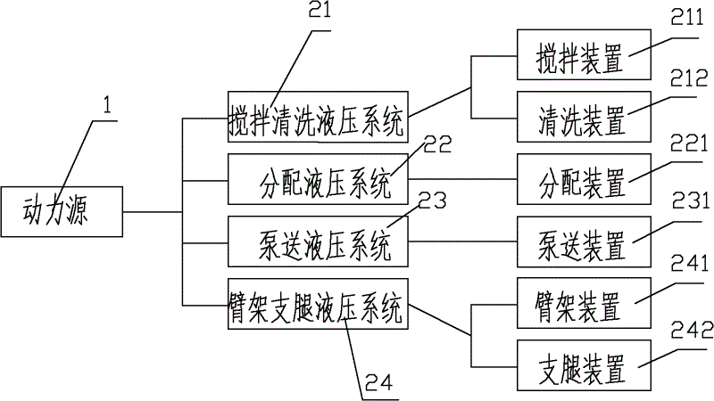
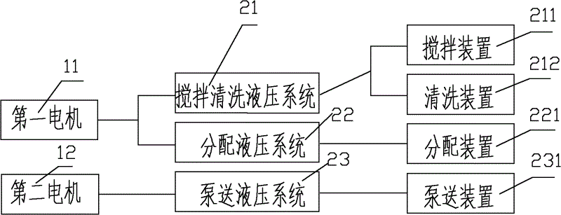
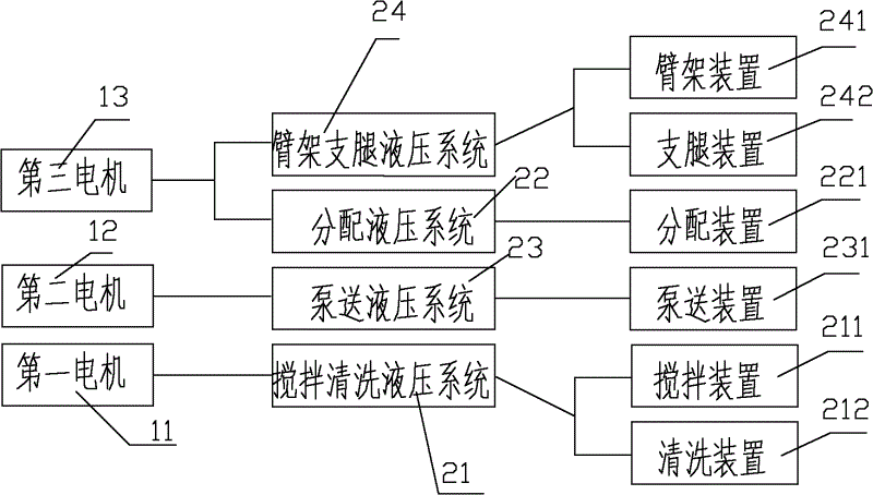
[0034] According to the basic inventive concept of the present invention, a concrete pumping equipment is provided, the concrete pumping equipment includes a plurality of working devices and a plurality of hydraulic systems for driving the plurality of working devices, and the plurality of hydraulic systems are composed of multiple Driven by a power source.

[0035] In the prior art, multiple hydraulic systems are only driven by one power source, so there are many defects and deficiencies as mentioned in the background art section. In order to overcome these defects and deficiencies, in the present invention, multiple power sources are used to drive multiple hy...


PUM


Abstract

The invention discloses concrete pumping equipment which comprises a plurality of working devices and a plurality of hydraulic systems for driving the working devices, wherein the hydraulic systems are driven by a plurality of power sources. The concrete pumping equipment is characterized in that the plurality of power sources are configured for the working devices to satisfy the wide power matching characteristic of each working device under various working conditions, the energy consumption can be lowered, the service life of a hydraulic element is prolonged, and the cost and weight for installing can be lowered.

Description

technical field [0001] The invention relates to engineering equipment, in particular to a concrete pumping equipment. Background technique [0002] At present, with the increasing difficulty of various concrete pumping projects, the structure of the concrete pumping equipment itself required to be used is also becoming more and more complex. Concrete pumping equipment usually includes trailer pumps and pump trucks. [0003] like figure 1 As shown, taking the pump truck as an example, the existing pump truck includes a plurality of working devices such as a stirring device 211, a cleaning device 212, a distribution device 221, a pumping device 231, a boom device 241 and a leg device 242, and these working devices Driven by a plurality of hydraulic systems to perform corresponding actions, these hydraulic systems include, for example, an agitation and cleaning hydraulic system 21 for driving a stirring device 211 and a cleaning device 212, a distribution hydraulic system 22 ...

Claims


Application Information

Patent Timeline
Patent Type & Authority Applications(China)
IPC IPC(8): E04G21/02
CPCF04B15/02E04G21/02
Inventor 万梁
Owner ZOOMLION HEAVY IND CO LTD
Why Eureka
Eureka Blog
Learn More