Connecting-rod opening and closing mechanism used for casement doors and windows and suspended sash windows

A technology for opening and closing mechanism and swinging doors and windows, which is applied in the direction of wing leaf operating mechanism, door/window accessories, wing leaf opener, etc. and other problems, to achieve the effect of fast opening and closing speed, large opening and closing force, and stable opening and closing speed

Inactive Publication Date: 2012-08-01
刘权熠
View PDF12 Cites 3 Cited by
  • Summary
  • Abstract
  • Description
  • Claims
  • Application Information

AI Technical Summary

Problems solved by technology

[0003] There are mainly three kinds of opening and closing devices currently visible: 1. The one-way bending chain drive is commonly used in the market, and the compound rotation action is realized by using the one-way bending characteristic of the one-way bending chain. The advantages of this scheme are obvious: the thrust is relatively Large, smooth movement, but the defects are also obvious: complex structure,

Method used


Image

  • Connecting-rod opening and closing mechanism used for casement doors and windows and suspended sash windows
  • Connecting-rod opening and closing mechanism used for casement doors and windows and suspended sash windows
  • Connecting-rod opening and closing mechanism used for casement doors and windows and suspended sash windows

Examples


specific Embodiment approach 1

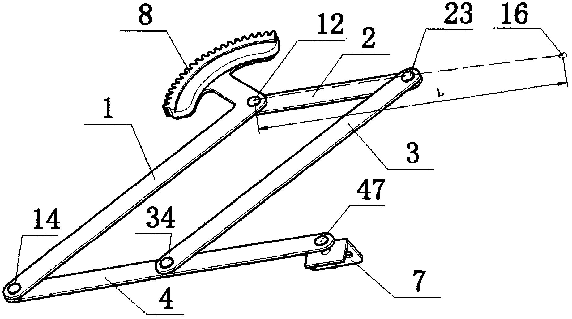
[0024] Specific implementation mode one: refer to figure 1 , the specific embodiment adopts the following technical scheme: it includes active rod 1, fixed rod 2, auxiliary rod 3, and push rod 4, and four connecting rods of active rod 1, fixed rod 2, auxiliary rod 3, and push rod 4 are sequentially hinged on the They are parallelograms together, the fixed rod 2 is fixed on the door and window frame 91, the active rod 1 is provided with a kinematic pair 8, the end of the push rod 4 is equipped with a connector 7, and the connector 7 is fixedly connected with the door and window sash 92, the first hinge point 12. The second hinge point 23 and the hinge shaft center 16 are on the same straight line, the distance between the first hinge point 12 and the hinge shaft center 16, the distance between the first hinge point 12 and the third hinge point 14 , the distances between the third hinge point 14 and the fourth hinge point 47 are equal.

[0025] The principle of the present inve...

specific Embodiment approach 2

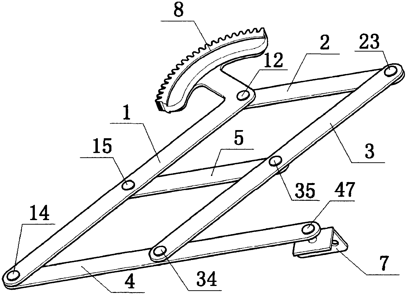
[0032] Specific implementation mode two: refer to figure 2 The difference between this specific embodiment and the first specific embodiment is that: the middle part of the active rod 1 and the auxiliary rod 3 is provided with a first connecting rod 5 parallel to the fixed rod 2 and the push rod 4, and the first connecting rod 5 The hinge points of the rod 5 , the active rod 1 and the auxiliary rod 3 are the sixth hinge point 15 and the seventh hinge point 35 respectively, and other components and connections are the same as those in the first embodiment.

[0033] In this specific embodiment, the stability of the connecting rod can be increased by adopting this method.

[0034] refer to Figure 5 , this specific embodiment uses a motor to provide power, and after the gear transmission mechanism shifts, the power is transmitted to the kinematic pair 8, and the kinematic pair 8 pushes the active rod 1 to rotate around the first hinge point 12, and then pushes the window sash t...

specific Embodiment approach 3

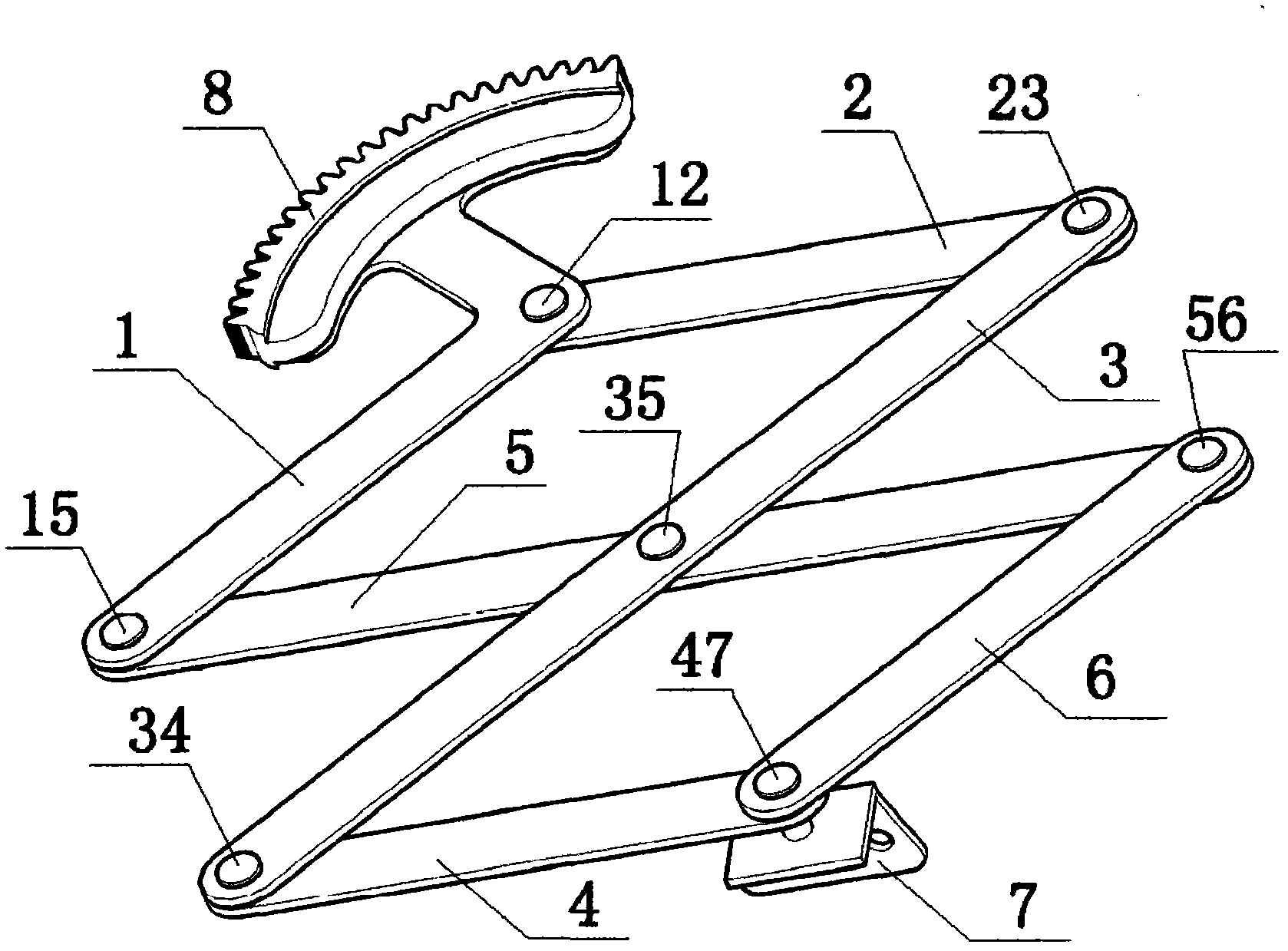
[0035] Specific implementation mode three: refer to image 3 The difference between this specific embodiment and the second specific embodiment is that: the first connecting rod 5 is extended, and the distance between the sixth hinge point 15 and the eighth hinge point 56 at both ends is the same as that between the first hinge point 12 and the second hinge point. The distance between the center of the hinge shaft 16 is equal, and the second connecting rod 6 is added at the eighth hinge point 56 and the fourth hinge point 47, and the hinge of the active rod 1 and the push rod 4 is released at the same time, and the active rod 1 and the push rod are shortened. The length of 4, other compositions and connections are the same as in the second embodiment.

[0036] This specific embodiment aims to form a compound hinge. By using this method, the length of the connecting rod after contraction can be reduced, and the opening and closing moment can be reduced.

[0037] refer to Ima...


PUM


Abstract

The invention discloses a connecting-rod opening and closing mechanism used for casement doors and windows and suspended sash windows and relates to the technical field of a door-window opening and closing mechanism. A kinematic pair is arranged on an active rod; a connecting piece which is fixedly connected with a door-window sash is arranged on the tip of a push rod; four connecting rods such as the active bar, a fixing bar, an auxiliary bar and the push bar are hinged successively to form a parallelogram; two hinge joints of the fixing rod and the center of the hinge spindle are in the same straight line and the distance between the hinge joints of the two ends of the active rod, the distance between the center of the hinge spindle and the hinge joint of the far end of the fixing rod and the distance between the hinge joints of the two ends of the push rod are equal, so that the connecting piece on the tip of the push rod is synchronous with the opening and closing of the door-window sash and the tracks completely coincide. The connecting-rod opening and closing mechanism can resolve the problems of the prior art and can realize the beneficial effects that opening and closing are rapid and stable, noise is low, push force is large, structure is simple, performance is reliable, power consumption is low and limitation of movement dead points is not generated.

Description

Technical field: [0001] The invention relates to the technical field of door and window opening and closing mechanisms, in particular to a connecting rod opening and closing mechanism for casement doors and windows and hanging windows, and in particular to a connecting rod opening and closing mechanism for electric, automatic or intelligent control of casement doors and windows / hung windows mechanism. Background technique: [0002] Electric, automatic or intelligent control of the opening and closing of casement doors and windows and hanging windows, the movement of fans is relatively simple, but it is more complicated for the opening and closing device to realize this action. The motion of the door and window is a simple rotary motion, but the opening and closing device needs to complete the compound rotary motion in order to realize the simple rotary motion of the door and window. [0003] There are mainly three kinds of opening and closing devices currently visible: 1. T...

Claims


Application Information

Patent Timeline
IPC IPC(8): E05F15/12E05F1/10F16H37/12E05F15/611
Inventor 刘权熠
Owner 刘权熠
Why Eureka
Try Eureka