Display apparatus, backlight module thereof, and method for assembling backlight module

A technology of backlight module and light source, which is applied to parts of lighting devices, lighting devices, fixed lighting devices, etc.

Active Publication Date: 2012-08-01
AU OPTRONICS CORP
View PDF6 Cites 3 Cited by
  • Summary
  • Abstract
  • Description
  • Claims
  • Application Information

AI Technical Summary

Problems solved by technology

[0004] When assembling, when the light source is installed on the light incident surface of the side of the light guide plate, if the light output surface of the light source is not close enough to the light incident surface of the

Method used


Image

  • Display apparatus, backlight module thereof, and method for assembling backlight module
  • Display apparatus, backlight module thereof, and method for assembling backlight module
  • Display apparatus, backlight module thereof, and method for assembling backlight module

Examples


Embodiment Construction

[0060] The following will clearly illustrate the spirit of the present invention with illustrations and detailed descriptions. After those skilled in the art understand the embodiments of the present invention, they can be changed and modified by the technology taught in the present invention, which does not depart from the present invention. spirit and scope.

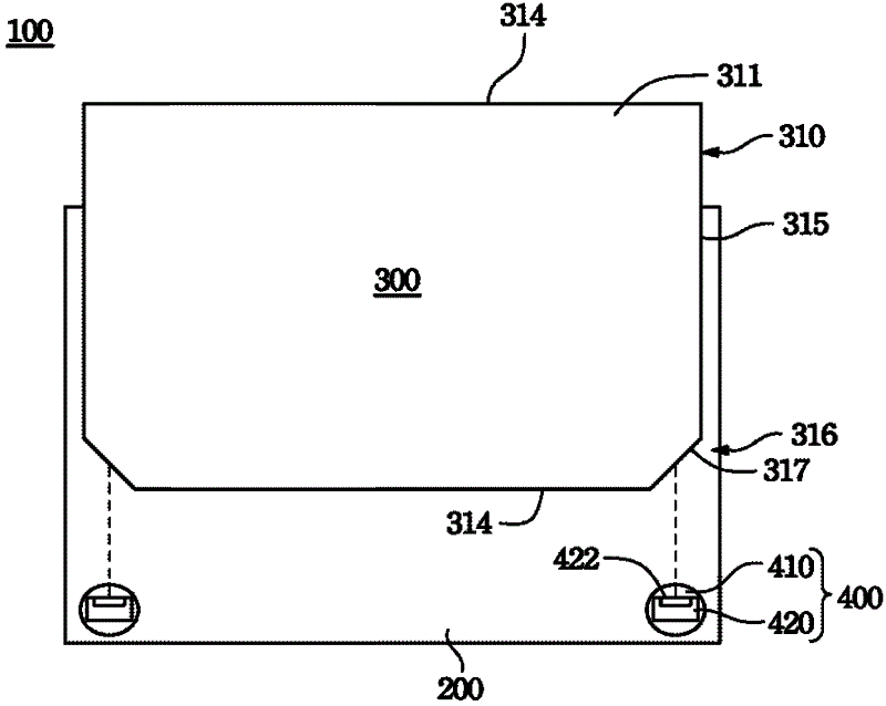
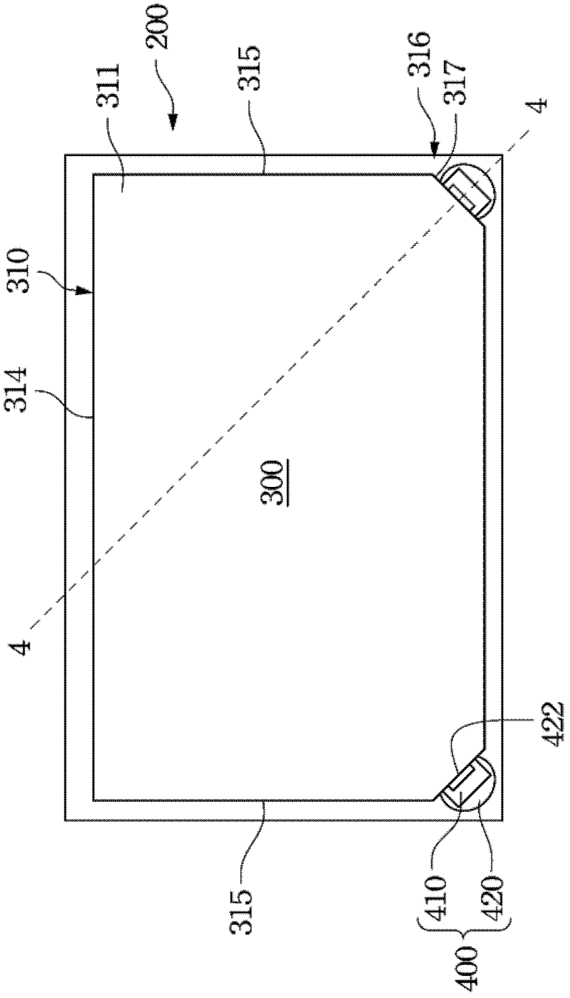
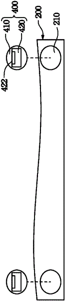
[0061] Since the light emitting surface of the light source is not close enough to the light incident surface on the side of the light guide plate, the gap between the light source and the light guide plate will reduce the light output efficiency of the light beam provided by the light guide plate.

[0062] In view of this, the present invention provides a backlight module. The light source is driven to rotate through the light guide plate, so that a light emitting surface of the light source is attached to the light incident surface along the inclined direction of a light incident surface of the notch portion of the l...


PUM


Abstract

The invention discloses a display apparatus, a backlight module thereof, and a method for assembling the backlight module. The backlight module comprises a pedestal, a light guide plate, and a light source, wherein the light guide plate comprises a corner-lacking portion; the light source can be arranged upon the pedestal in a rotary manner; and one lighting surface of the light source is applied to one light-incoming surface of the corner-lacking portion.

Description

technical field [0001] The invention relates to a backlight module, in particular to a backlight module in which the light emitting surface of a light source is attached to the light incident surface of a light guide plate. Background technique [0002] The Back Light Module (Back Light Module) is a key component of a Liquid Crystal Display (LCD), through which a light source with sufficient brightness and uniformity is supplied to enable the Liquid Crystal Panel (Liquid Crystal Panel) to display images. Backlight modules can be roughly divided into "side-lit" and "direct-lit" designs according to the position of the light source. [0003] As far as the backlight module with "side-light" design is concerned, the backlight module with "side-light" design installs the light source on the light incident surface on one side of the light guide plate, so that the light source can enter the light guide plate toward the light incident surface, and then pass through the light guide p...

Claims


Application Information

Patent Timeline
IPC IPC(8): F21S8/00F21V8/00F21V19/02G02F1/13357
Inventor 简元禹
Owner AU OPTRONICS CORP
Why Eureka
Try Eureka