
Method for improving uniform distribution of light sources and structure thereof

A uniform distribution and light source technology, applied in the direction of light source, fixed light source, point light source, etc., can solve problems such as uneven light source and shadow, image shadow, and affecting the accuracy of system recognition

Inactive Publication Date: 2011-08-10
MILLENNIUM COMM
View PDF0 Cites 2 Cited by
  • Summary
  • Abstract
  • Description
  • Claims
  • Application Information

AI Technical Summary

Problems solved by technology

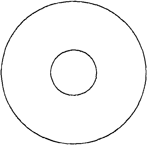
However, when using a high-power surface-emitting laser chip or an edge-emitting laser chip, the laser output light source presents a donut shape with a darker center due to the limitation of its output light shape, such as Figure 1C As shown, there will be shadows in the image due to the uneven brightness of the light source
When it is applied to identify human figures or license plate numbers, this laser light source may affect the accuracy of system identification
Usually, the problem of unevenness of the light source can be overcome by using additional diffusion film or other optical conversion, but this method requires additional cost and will reduce the light extraction efficiency of the light source

Method used

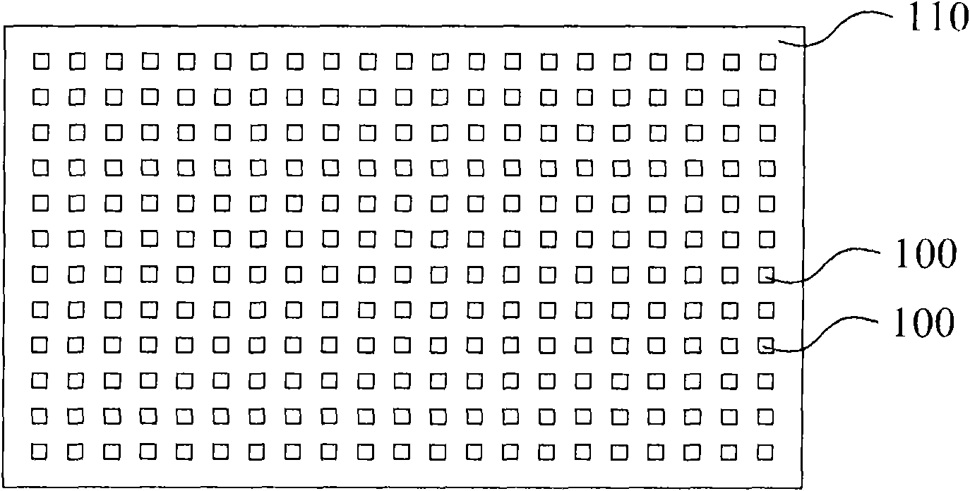
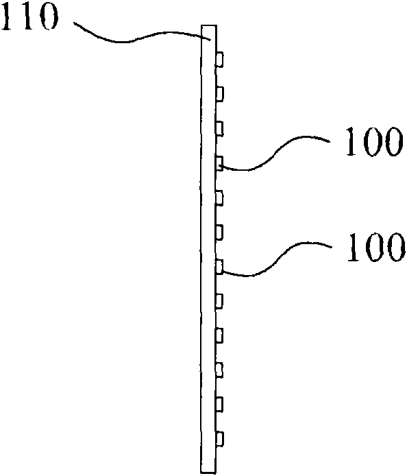

Image

  • Method for improving uniform distribution of light sources and structure thereof
  • Method for improving uniform distribution of light sources and structure thereof
  • Method for improving uniform distribution of light sources and structure thereof

Examples


Embodiment Construction

[0016] Its detailed description is as follows, and the preferred embodiment is only to illustrate the present invention by way of enumeration, but not to limit the present invention.

[0017] figure 2 It is a schematic flowchart of a method for improving uniform distribution of light sources according to an embodiment of the present invention. Such as figure 2 As shown, the method includes the following steps: providing a base with at least one curved surface (step S101); and disposing a plurality of light source chips on the curved surface (step S102). Wherein, the light source chip can be selected from a light emitting diode chip or a laser chip, and the laser chip can be a side-firing laser chip or a side-firing laser chip.

[0018] image 3 It is a schematic flow chart of a method for improving the uniform distribution of light sources according to an embodiment of the present invention. Step S103 is to arrange a plurality of light source chips on a curved surface, wh...


PUM


Abstract

The invention relates to a method for improving the uniform distribution of light sources and a structure thereof. The method for improving the uniform distribution of the light sources and the structure thereof are that through arranging a plurality of light source chips on a base of at least one curved surface, each light beam emitted by each light source chip can be partially superposed and are further mutually compensated in light shape to obtain the uniform and bright light sources. Therefore, through the method, the uniform light sources can be obtained without optical element, so that the cost can be effectively controlled, and good light emitting efficiency can be maintained.

Description

technical field [0001] The invention relates to a method for improving uniform distribution of light sources and its structure. Background technique [0002] Due to home security or business needs, infrared photographic surveillance systems or identification systems have been widely used, generally using several high-power light-emitting diodes as their lighting sources. In view of the prevalence of environmental protection and caring for the earth, energy-saving and carbon-reducing technologies are constantly being researched to develop more alternative products, and laser light sources are also used in infrared surveillance systems for lighting. [0003] Generally, the power of high-power light-emitting diodes used in infrared photographic surveillance systems or identification system lighting requires about 300 watts. However, if you choose to use a laser light source, the required power can be reduced to 40 watts to obtain the same lighting effect, which can effectively ...

Claims


Application Information

Patent Timeline
Patent Type & Authority Applications(China)
IPC IPC(8): F21V19/00F21Y101/02F21Y115/10
Inventor 张瑞聪赖利弘赖利温许立民
Owner MILLENNIUM COMM
Learn More