
Aspheric surface adjustment error compensation method for sub-aperture stitching detection

A technology of sub-aperture splicing and error adjustment, applied in the field of optical detection, can solve problems such as deviation in relative positional relationship, and achieve the effect of accurate splicing detection

Active Publication Date: 2012-08-01
CHANGCHUN INST OF OPTICS FINE MECHANICS & PHYSICS CHINESE ACAD OF SCI
View PDF2 Cites 16 Cited by
  • Summary
  • Abstract
  • Description
  • Claims
  • Application Information

AI Technical Summary

Problems solved by technology

However, during the splicing measurement process, the actual relative positional relationship between the interferometer and the aspheric surface to be measured will definitely deviate from the theoretical relative positional relationship.

Method used


Image

  • Aspheric surface adjustment error compensation method for sub-aperture stitching detection
  • Aspheric surface adjustment error compensation method for sub-aperture stitching detection
  • Aspheric surface adjustment error compensation method for sub-aperture stitching detection

Examples


Embodiment Construction

[0018] The present invention will be described in further detail below in conjunction with the accompanying drawings and embodiments.

[0019] A sub-aperture splicing detection aspheric adjustment error compensation method, the method includes the following steps:

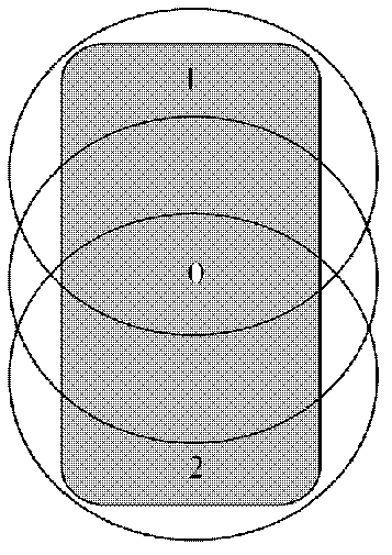
[0020] Step 1: Set the interferometer so that the radius of curvature of the reference spherical wavefront coincides with the radius of the closest spherical surface in the central area of ​​the aspheric surface to be measured, that is, to measure the phase distribution of the central reference sub-aperture;

[0021] Step 2: Adjust the relative positional relationship between the interferometer and the aspheric surface to be measured, so that the wavefront of the standard spherical surface of the interferometer is aligned with the area to be measured on the aspheric surface, that is, to measure the phase distribution of other sub-apertures;

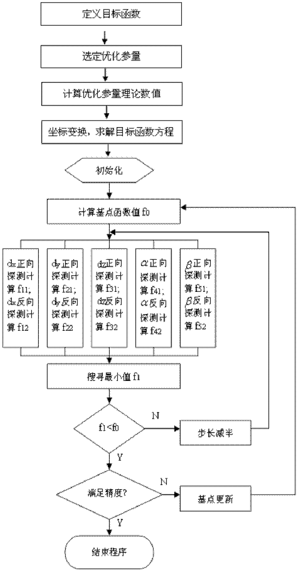
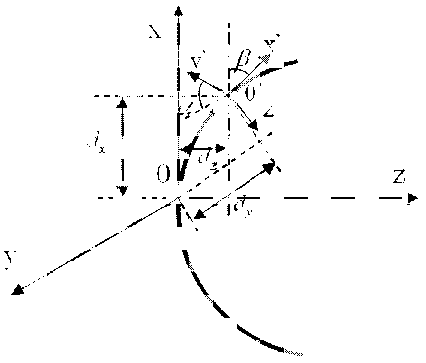
[0022] Step 3: Eliminate the adjustment error generated when the standard...


PUM


Abstract

An aspheric surface adjustment error compensation method for sub-aperture stitching detection relates to the field of optical detection, and includes the steps: setting an interferometer to lead the curvature radius of a reference sphere wave front of the interferometer to be matched with the closest spherical radius of a central area of a to-be-detected aspheric surface; adjusting the relative position relation of the interferometer with the to-be-detected aspheric surface, so that the standard spherical wave front of the interferometer is aligned with a to-be-detected aspheric surface area; by means of a pattern search error compensation method, eliminating adjustment errors generated when the standard spherical surface detects the to-be-detected aspheric surface with large deviation amount; and realizing full-aperture stitching detection to obtain a precise surface-shaped result by means of the sub-aperture stitching detection technology. By means of the pattern search error compensation method, the adjustment errors resulting from nonalignment of stitching measurement positions can be effectively eliminated from measured sub-aperture phase data, so that stitching of multiple sub-apertures can be effectively realized, and aspheric surface full-aperture surface-shaped stitching detection can be precisely completed.

Description

technical field [0001] The invention relates to the field of optical detection, in particular to a sub-aperture splicing detection aspheric adjustment error compensation method. Background technique [0002] The use of aspheric elements in optical systems and optical instruments can correct aberrations, improve image quality, and reduce the size and weight of optical systems. Therefore, aspheric elements are increasingly being used in astronomy, space optics, and military National defense, high-tech civil and other fields, the detection of aspherical components has gradually attracted attention. [0003] The sub-aperture stitching is to use the small-aperture standard spherical reference wavefront of the interferometer to measure the phase of each area on the large-aperture aspheric surface successively, and the full-aperture surface information of the aspheric surface can be obtained through the sub-aperture stitching algorithm. The sub-aperture splicing technology broaden...

Claims


Application Information

Patent Timeline
Patent Type & Authority Applications(China)
IPC IPC(8): G01B11/24
Inventor 王孝坤
Owner CHANGCHUN INST OF OPTICS FINE MECHANICS & PHYSICS CHINESE ACAD OF SCI
Learn More