Catadioptric long-focal-length large-view-field small-size imaging optical system

An imaging optics and long focal length technology, applied in optics, optical components, instruments, etc., can solve the problems of large back intercept, small field of view, and limited use, so as to reduce the system volume, increase the system focal length, and realize The effect of focal plane stitching

Inactive Publication Date: 2020-08-04
BEIJING RES INST OF SPATIAL MECHANICAL & ELECTRICAL TECH
View PDF1 Cites 12 Cited by
  • Summary
  • Abstract
  • Description
  • Claims
  • Application Information

AI Technical Summary

Problems solved by technology

Using this method, since the positive and negative lens groups do not produce focal power, the correction of field curvature can only rely on the negative field lens in front of the focal point, resulting in a small field of view and a short back intercept. The use of products with large back focus for image plane optical stitching is limited
[0005] 2) The off-axis three-mirror system uses three off-axis mirrors to achieve a large field of view of the line array, and has the advantages of no chromatic aberration and a large back intercept, but this system can only achieve a larger field of view in the direction of the line array. The field of view in one direction is small, which is not suitable for area staring or video imaging, and the off-axis reflective system is larger and heavier than the coaxial reflective system
[0006] 3) Telephoto transmission system, this system adopts the telephoto structure with the positive lens behind the front and rear lens groups, which can achieve a larger field of view and a shorter system length than the focal length, but due to the limitation of the transmission structure, this system The length of the system will be much longer than that of a reflective system
And because the transmission system is not suitable for the system with a long focal length due to the limitation of the lens aperture

Method used


Image

  • Catadioptric long-focal-length large-view-field small-size imaging optical system
  • Catadioptric long-focal-length large-view-field small-size imaging optical system
  • Catadioptric long-focal-length large-view-field small-size imaging optical system

Examples


Embodiment Construction

[0022] Exemplary embodiments of the present disclosure will be described in more detail below with reference to the accompanying drawings. Although exemplary embodiments of the present disclosure are shown in the drawings, it should be understood that the present disclosure may be embodied in various forms and should not be limited by the embodiments set forth herein. Rather, these embodiments are provided for more thorough understanding of the present disclosure and to fully convey the scope of the present disclosure to those skilled in the art. It should be noted that, in the case of no conflict, the embodiments of the present invention and the features in the embodiments can be combined with each other. The present invention will be described in detail below with reference to the accompanying drawings and examples.

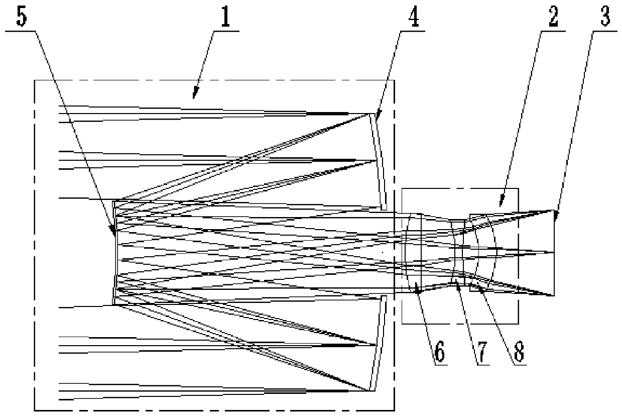
[0023] figure 1 It is a schematic diagram of a catadioptric long focal length large field of view small volume imaging optical system provided by an embodime...


PUM


Abstract

The invention discloses a catadioptric long-focal-length large-view-field small-size imaging optical system. The catadioptric long-focal-length large-view-field small-size imaging optical system comprises a front group positive-focal-power reflection type optical group and a rear group negative-focal-power transmission type optical group. The front group positive-focal-power optical system comprises a concave primary mirror reflector and a convex secondary mirror reflector; and the rear group negative-focal-power transmission type optical group is composed of a positive lens group, a negativelens group and a small focal power meniscus lens. An object imaging light beam is reflected by the concave primary mirror reflector and the convex secondary mirror reflector in sequence, then enters atransmission-type system, is refracted by the positive lens group, the negative lens group and the small focal power meniscus lens in sequence, and then is imaged on an image plane. In the invention,requirements of a high resolution, a large breadth range and a small size and weight of a space camera are met.

Description

technical field [0001] The invention belongs to the technical field of optical imaging systems, in particular to a catadioptric-based long focal length large field of view small volume imaging optical system. Background technique [0002] With the increase of aerospace space exploration missions, the observation requirements and volume weight of aerospace cameras are also getting higher and higher. For example, the higher resolution of satellite imaging results in a focal length generally greater than 500mm, and the larger camera field of view needs to be 3°~ 6°, due to the increase in width requirements, the number of detectors has also changed from one piece to multi-piece splicing. At the same time, the requirements for camera weight and volume are becoming more and more stringent. [0003] The existing implementation methods mainly include the following: [0004] 1) A catadioptric system with no-refractive lens group is used, and a negative field lens is used to correc...

Claims


Application Information

Patent Timeline
Patent Type & Authority Applications(China)
IPC IPC(8): G02B17/08G03B17/17
CPCG02B17/082G03B17/17
Inventor 佟静波吴建福侯作勋张青春陈彦潘铮胡永富张宏伟刘明李馨高原肖可平赵兴成田建柱张原野张保贵
Owner BEIJING RES INST OF SPATIAL MECHANICAL & ELECTRICAL TECH
Why Eureka
Try Eureka