

Cable laying method and bracket thereof
A cable laying and cable technology, which is applied in the field of cable laying and its support, can solve the problems of difficulty, large longitudinal induced voltage of cable aluminum sheath, etc., and achieve the effects of reducing induced voltage, good energy saving effect, and reducing civil construction costs
- Summary
- Abstract
- Description
- Claims
- Application Information
AI Technical Summary
Problems solved by technology
Method used
Image

Examples
Embodiment Construction
[0023] The present invention will be further described below in conjunction with accompanying drawing.
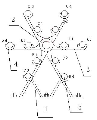
[0024] Such as figure 1 As shown, the cable laying bracket of the present invention includes a bracket main body 1, and twelve cable support seats 2 and a central ring 3 arranged on the support main body 1, and every three cable support seats 2 form a group, and the cable support seats 2 Arranged along the circumferential direction of the concentric circles, and the same group of cable support seats 2 are located on the same circumference, and the angle between them is 120°; the central ring 3 is located at the center of the aforementioned concentric circles; the concentric circles include inner rings And the outer ring, six cable support seats 2 are respectively established on the inner and outer rings, and are evenly arranged along the inner and outer rings.
[0025] When in use, four sets of three-phase cables can be placed on the cable laying bracket to place the cable...
PUM
 Abstract
Description
Claims
Application Information