Heat radiation type joint

A heat-dissipating and heat-dissipating space technology, which is applied in the direction of connecting contact materials, clamping/spring connections, cooling busbar devices, etc., can solve the problems of high cost of converting fittings, blown tube busbars, waste of materials, etc., and achieves light weight, Increase the heat dissipation space and reduce the effect of temperature rise

Inactive Publication Date: 2006-11-08
罗东豪
View PDF0 Cites 0 Cited by
  • Summary
  • Abstract
  • Description
  • Claims
  • Application Information

AI Technical Summary

Problems solved by technology

[0002] The existing conductive tube busbar joints have the following disadvantages in the actual installation process: Since the conductive tube busbar is circular, it is necessary to install conversion fittings during the connection process with the equipment, from a round surface to a flat surface, and connect to other equipment through a rectangular conductor
1. The connection between the pipe busbar and the equipment needs to be equipped with conversion fittings, which is costly, wastes materials, and consumes energy
2. The connection between the end of the pipe busbar and the conversion fitting will generate contact resistance. Due to the existence of contact resistance, in the case of high current transmission, the end of the pipe busbar and the conversion fitting will generate excessive heat. The greater the heat, the higher the resistance , the more serious the heat is, the higher the temperature will cause the pipe busbar to be blown, short circuit between phases, short circuit to ground or cause a fire and cause a greater accident

Method used


Image

  • Heat radiation type joint
  • Heat radiation type joint

Examples


Embodiment Construction

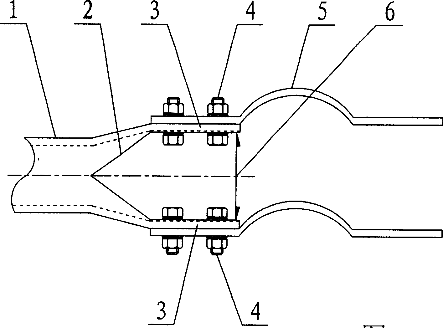
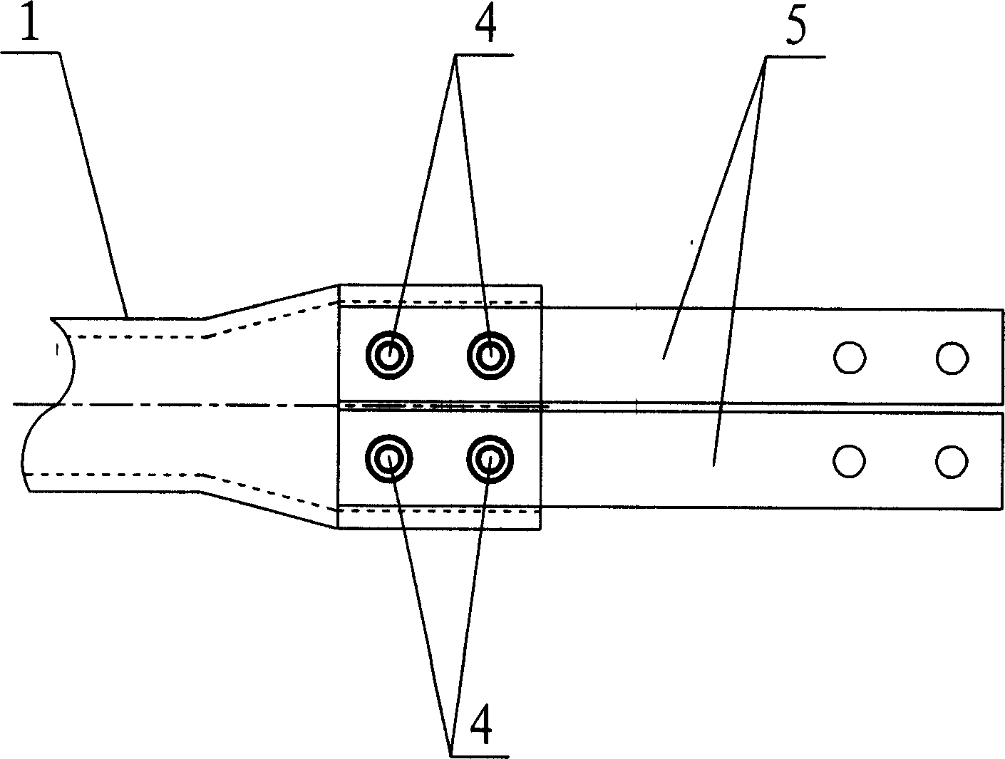
[0009] The specific embodiments of the present invention will be further described below in conjunction with the accompanying drawings.

[0010] like figure 1 As shown, the heat-dissipating joint of the present invention is to divide the end of the pipe busbar (about twice the length of the pipe busbar diameter) into two semicircles, and then stamp the two semicircles with a stamping process to form two rectangular plane conductive bars, There are reinforcing ribs on both sides of the two rectangular plane conductive bars, and there is a certain heat dissipation space distance between the two rectangular plane conductive bars, and then the two rectangular plane conductive bars formed by stamping are connected to other equipment through rectangular conductors, which forms a heat dissipation type heat sink connector.


PUM


Abstract

This invention relates to a heat radiation connector, in which, two rectangle plane conduction rows are set at the end of its pipe bus and a gap is between them, 1, easy to be connected with other equipments, 2, increasing radiation space, 3, favorable of reducing temperature-rising of the end of the connector, 4, no contact resistance since it is integrated without connection position and the end of the bus will not generate high temperature and since the connector is an integrated one, the original conversion metal is removed.

Description

technical field [0001] The heat-dissipating joint of the invention is especially suitable for connecting the busbars of conductive pipes that transmit power-frequency and large currents. Large current carrying capacity, low temperature rise, high mechanical strength, and improved operating safety factor. Background technique [0002] The existing conductive tube busbar joints have the following disadvantages in the actual installation process: Since the conductive tube busbar is circular, it is necessary to install conversion fittings during the connection process with the equipment, from a round surface to a flat surface, and connect to other equipment through a rectangular conductor . 1. It is necessary to install conversion fittings to connect the pipe busbar to the equipment, which is costly, wastes materials and consumes energy. 2. The connection between the end of the pipe busbar and the conversion fitting will generate contact resistance. Due...

Claims


Application Information

Patent Timeline
Patent Type & Authority Applications(China)
IPC IPC(8): H02G5/10H01R4/28H01R4/60
Inventor 罗东豪
Owner 罗东豪
Why Eureka
Try Eureka