Method for improving digital monitoring precision of optical power on receiving end of passive optical network optical line terminal (PON OLT) optical module

A digital monitoring and optical module technology, applied in the field of optical communication, can solve the problems of large monitoring error and failure to meet the monitoring accuracy requirements of PONOLT optical power at the receiving end, so as to improve the monitoring accuracy, reduce the internal minimum unit, and narrow the monitoring range Effect

Active Publication Date: 2012-08-01
SOURCE PHOTONICS CHENGDU
View PDF3 Cites 2 Cited by
  • Summary
  • Abstract
  • Description
  • Claims
  • Application Information

AI Technical Summary

Problems solved by technology

[0011] The purpose of the present invention is to provide a method for improving the digital monitoring accuracy of optical power at the receiving end of a PON OLT optical module, so as to solve the problem of large monitoring errors when the minimum continuous receiving optical power monitoring unit is 0.1uW defined by the traditional SFF-8472 protocol. , can not meet the PON OLT receiving end optical power monitoring accuracy requirements

Method used


Image

  • Method for improving digital monitoring precision of optical power on receiving end of passive optical network optical line terminal (PON OLT) optical module
  • Method for improving digital monitoring precision of optical power on receiving end of passive optical network optical line terminal (PON OLT) optical module
  • Method for improving digital monitoring precision of optical power on receiving end of passive optical network optical line terminal (PON OLT) optical module

Examples


Embodiment Construction

[0027] The technical solutions in the embodiments of the present invention will be clearly and completely described below. Obviously, the described embodiments are only some of the embodiments of the present invention, but not all of them. Based on the embodiments of the present invention, all other embodiments obtained by persons of ordinary skill in the art without creative efforts fall within the protection scope of the present invention.

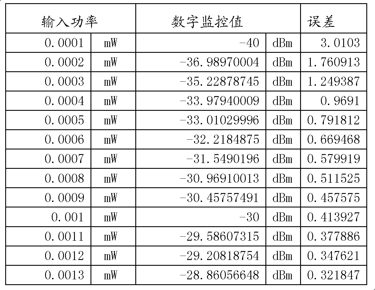
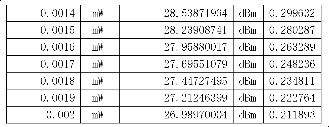
[0028] According to the introduction of the background technology, when monitoring with the minimum continuous receiving optical power monitoring unit of 0.1uW defined by the traditional SFF-8472 protocol, the monitoring error is large, which cannot meet the PON OLT receiving end optical power monitoring accuracy requirements.

[0029] Since the SFF-8472 protocol takes 0.1uW as the minimum unit, the digital monitoring value is stored by a 16bit register, the counting range is 0~65535, the monitoring range is 0~6.5mW, the maximum monitorin...


PUM


Abstract

The invention discloses a method for improving digital monitoring precision of optical power on a receiving end of a passive optical network optical line terminal (PON OLT) optical module. The method is based on a small form factor-8472 (SFF-8472) protocol, at least four continuous bytes in reserved bytes of the SFF-8472 protocol are selected and are defined as calibration bytes, a float-point number with single precision in the calibration bytes is adopted as a calibration value, and the calibration value is more than 1 but less than 10; a digital monitored sample value of the input power monitored by a digital diagnostics monitoring interface (DDMI) is divided by the calibration value to obtain the calibrated input power sample value, so that the monitoring precision can be effectively improved. Under the situation that a number register is not changed, the monitoring range is narrowed, so that the internal minimal unit is reduced, the error can be effectively reduced, and the monitoring precision requirement of the optical power on the receiving end of the PON OLT can be met.

Description

technical field [0001] The invention relates to the field of optical communication, in particular to a method for improving the precision of digital monitoring of optical power at the receiving end of a PON OLT optical module. Background technique [0002] The continuous receiving optical power monitoring of the traditional SFF-8472 protocol takes 0.1uW as the minimum unit, and the monitoring range is 0~6.5mW. The digital monitoring value is stored by a 16bit register, and the counting range is 0~65535. This solution has two problems for the monitoring of the burst receiving power of the passive optical network terminal PON OLT: [0003] 1) When the input optical power is less than -30dBm, the digital monitoring accuracy error becomes worse as the input power decreases, and for the OLT (Optical Line Terminal, optical cable terminal equipment) of the PON (Passive Optical Network, passive optical network) system The received power may be as low as -34dBm, and the monitoring e...

Claims


Application Information

Patent Timeline
Patent Type & Authority Applications(China)
IPC IPC(8): H04B10/08H04Q11/00H04B10/071H04B10/079
Inventor 蒋旭帅欣鞠兵
Owner SOURCE PHOTONICS CHENGDU
Why Eureka
Try Eureka