Method for detecting conductor position and grid structure of transformer station grounding network
A grid structure and detection method technology, applied in the detection field, can solve the problems of lowering the grounding performance, thinning the grid conductor, destroying the original structure of the grounding grid, etc., and achieve the effect of simple operation and labor saving
Inactive Publication Date: 2012-08-08
STATE GRID CORP OF CHINA +1
View PDF4 Cites 18 Cited by
- Summary
- Abstract
- Description
- Claims
- Application Information
AI Technical Summary
Problems solved by technology
However, due to corrosion and other reasons, the grid conductor may become thinner or breakpoints may appear, destroying the original structure of the grounding grid, reducing the grounding performance, and losing the protection function
[0003] The design and laying drawings of the grounding grid are the prerequisites for finding breakpoints and severely corroded sections of the grounding grid, as well as conducting
Method used
View moreImage
Smart ImageViewing Examples
Examples
 PUM
 Abstract
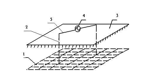
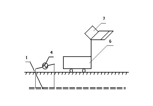
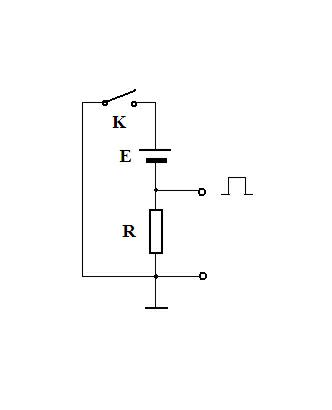
The invention relates to a method for detecting the position of an underground conductor and the grid structure of a transformer station grounding network under the normal running condition of a transformer station. The method comprises the following steps of: 1, connecting a sine wave current source between two lower guide bodies at appropriate positions by using existing lower guide body wires on the ground surface; 2, constructing a right-angle coordinate system in a horizontal direction by taking a current injection point as an original point; 3, measuring ground surface magnetic induction strengths along an x direction and a y direction respectively, and recording position coordinates where peak values appear simultaneously; and 4, reversely calculating a grounding network structure according to a measured result and the peak value coordinate, and drawing a structure diagram of the grounding network to judge the positioned of a buried conductor and the grid structure of the grounding network. The detection system consists of a detection signal generating part and a signal detection part. According to the method, the underground conductor, position and structure of the transformer station grounding network can be detected rapidly and accurately under the normal running condition of a transformer station, and the problems of loss and defect of a drawing of the transformer station grounding network are solved.
Description
technical field [0001] The invention belongs to the technical field of detection, and in particular relates to a detection method capable of efficiently, simply and accurately detecting the position and grid structure of an underground conductor of a substation grounding grid under the condition of normal operation of a substation. Background technique [0002] The grounding grid plays a very important role in the safe operation of the substation. It not only provides a common reference ground for various electrical equipment in the substation, but also quickly discharges the fault current and reduces the ground potential in the substation when the system fails or is struck by lightning. To protect the personal safety of the staff in the substation and the safety and normal operation of various electrical equipment. The grounding device is generally a grid-like grounding body, which is usually welded with flat steel, round steel, angle steel, steel pipe or copper materials t...
Claims
Login to View More Application Information
Patent Timeline
 IPC IPC(8): G01R31/00G01R33/02
Inventor 武建华付伟平隋少臣赵京武葛乃榕张智白剑忠李增福尹子会邢建刚霍春燕段剑常浩
Owner STATE GRID CORP OF CHINA
Features
- R&D
- Intellectual Property
- Life Sciences
- Materials
- Tech Scout
- Unparalleled Data Quality
- Higher Quality Content
- 60% Fewer Hallucinations
Learn More Browse by: Latest US Patents, China's latest patents, Technical Efficacy Thesaurus, Application Domain, Technology Topic, Popular Technical Reports.
© 2025 PatSnap. All rights reserved.Legal|Privacy policy|Modern Slavery Act Transparency Statement|Sitemap|About US| Contact US: help@patsnap.com


