Current collector for manipulator
A manipulator and collector technology, applied in the field of collectors for manipulators, can solve problems such as being unsuitable for manipulator applications, and achieve the effect of reducing electrical failures and ensuring cleanliness.
- Summary
- Abstract
- Description
- Claims
- Application Information
AI Technical Summary
Problems solved by technology
Method used
Image
Examples
Embodiment
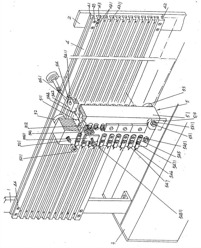
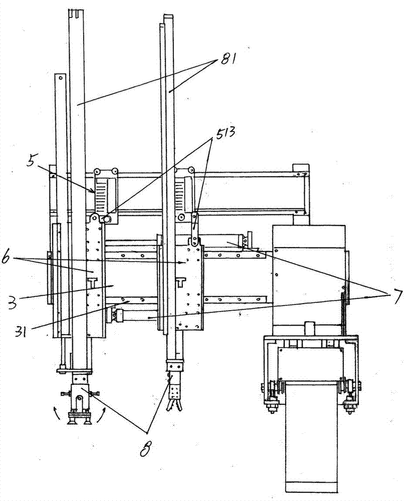
[0013] See figure 1 , shows the cross arm 3 of the manipulator. According to the known technology, the execution parts of the manipulator are usually installed on the cross arm 3 . A first support 1 and a second support 2 are fastened longitudinally parallel to each other on the transverse arm 3 . One end (the left end in the drawing) of a conductive strip fixing plate 4 is fixed on the first support 1 with the first screw 44 , and the other end (the right end in the drawing) is fixed on the second support 2 with the second screw 45 . An upper roller groove 41, a lower roller groove 42 and a group of conductive strip grooves 43 between the upper and lower roller grooves 41, 42 are formed on the side of the conductive strip fixing plate 4 facing the current collector 5 described below. Depend on figure 1 As shown, the upper and lower roller grooves 41, 42 and the conductive strip groove 43 all pass through from one end (left end) to the other end (right end) of the lengt...
PUM
 Abstract
Description
Claims
Application Information
 - R&D
- Intellectual Property
- Life Sciences
- Materials
- Tech Scout
- Unparalleled Data Quality
- Higher Quality Content
- 60% Fewer Hallucinations
Browse by: Latest US Patents, China's latest patents, Technical Efficacy Thesaurus, Application Domain, Technology Topic, Popular Technical Reports.
© 2025 PatSnap. All rights reserved.Legal|Privacy policy|Modern Slavery Act Transparency Statement|Sitemap|About US| Contact US: help@patsnap.com


