Rotor for electric rotating machine

A technology for rotating electrical machines and rotors, which is applied in the direction of electromechanical devices, electrical components, and electric components. It can solve problems such as no flow, ineffective use of the iron core area, and unsmooth q-axis magnetic flux, so as to achieve reactive torque increase. The effect of large, high torque output, and increased q-axis inductance

Inactive Publication Date: 2012-08-08
TOYOTA JIDOSHA KK +2
View PDF6 Cites 9 Cited by
  • Summary
  • Abstract
  • Description
  • Claims
  • Application Information

AI Technical Summary

Problems solved by technology

[0007] Another problem is that, since the q-axis magnetic flux does not flow smoothly or at all through the substantially triangular core region 92 which is the central portion of the q-axis magnetic path, it cannot efficiently use area of ​​core area

Method used


Image

  • Rotor for electric rotating machine
  • Rotor for electric rotating machine
  • Rotor for electric rotating machine

Examples


Embodiment Construction

[0020] Hereinafter, embodiments of the present invention are described in detail with reference to the accompanying drawings. It should be noted that specific shapes, materials, numerical values, directions, etc. in this specification are examples for helping understanding of the present invention, and may be changed according to requirements of usage, purpose, specification, etc.

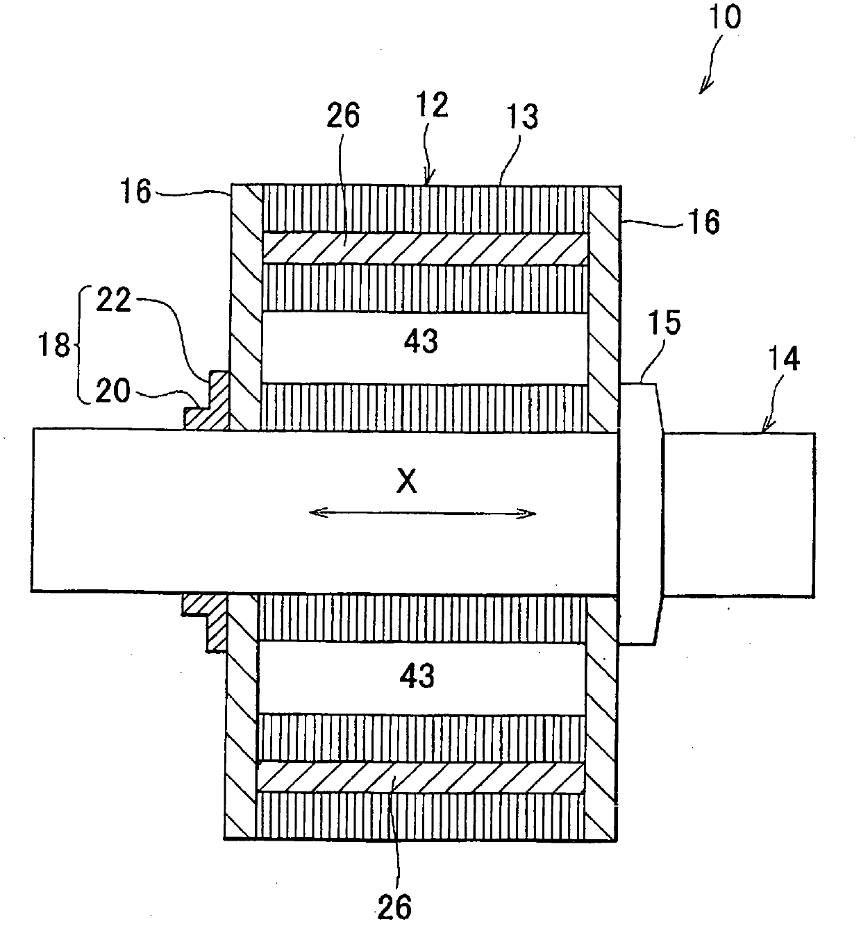
[0021] figure 1 is an axial sectional view of a rotor 10 for a rotating electric machine (the rotor 10 may be simply referred to as a "rotor" hereinafter as necessary) of this embodiment. A cylindrical stator (not shown) is provided around the rotor 10 . The stator forms a magnetic field that rotatably drives the rotor 10 .

[0022] The rotor 10 comprises a cylindrical or cylindrically-column-shaped rotor core 12 having: a central hole; a shaft 14 extending fixedly through the central hole of the rotor core 12; end plates 16, The end plate 16 is arranged to be in contact with both sides of the r...


PUM


Abstract

The invention relates to a rotor for an electric rotating machine. An iron rotor core includes a first permanent magnet in an outer peripheral portion of the iron rotor core, second permanent magnets on both circumferential sides of the first permanent magnet and arranged in a generally V-shaped configuration opening radially outward, and a first region provided opposite to the first permanent magnet radially inside the region between the second permanent magnets and having a low magnetic permeability. A q-axis magnetic flux path is formed in an iron core region among the first permanent magnet, the second permanent magnets and the first region, and a central portion thereof is formed between the first permanent magnet and the first region, and entrance / exit portions of the q-axis magnetic flux path formed between the second permanent magnets and second regions provided on both circumferential sides of the first permanent magnet and having a low magnetic permeability with generally the same width.

Description

technical field [0001] The present invention relates to a rotor for a rotating electrical machine, and more particularly to a rotor for a rotating electrical machine comprising a plurality of permanent magnets embedded in a circumferentially spaced relationship in a rotor core. in the peripheral part. Background technique [0002] As a related art, for example, a rotor 80 for a motor as shown in FIG. 3 is known, which is disclosed in Japanese Patent Application Publication No. 2003-134704 (JP-A-2003-134704). FIG. 3 is a view illustrating a part of the rotor 80 , in other words, the part is a quarter (90° area) of the cross section of the rotor 80 perpendicular to the axis of the shaft 82 . [0003] In FIG. 3 , a rotor 80 includes: a shaft 82 that is rotatably supported as a rotating shaft of the rotor; a rotor core 84 fixed to the shaft 82; a plurality of permanent magnets 86 (shown in FIG. only one of the plurality of permanent magnets 86), the permanent magnet 86 is arra...

Claims


Application Information

Patent Timeline
Patent Type & Authority Applications(China)
IPC IPC(8): H02K1/27
CPCH02K1/2766
Inventor 佐野新也武田健稻垣智广大竹新一宫路刚渡边裕太吉田稔彦齐藤洋一
Owner TOYOTA JIDOSHA KK
Why Eureka
Try Eureka