

Hub generator for bicycle
A hub generator and bicycle technology, applied to bicycle accessories, bicycle brakes, hubs, etc., can solve problems such as difficult wiring
- Summary
- Abstract
- Description
- Claims
- Application Information
AI Technical Summary
Problems solved by technology
Method used
Image

Examples
no. 1 Embodiment
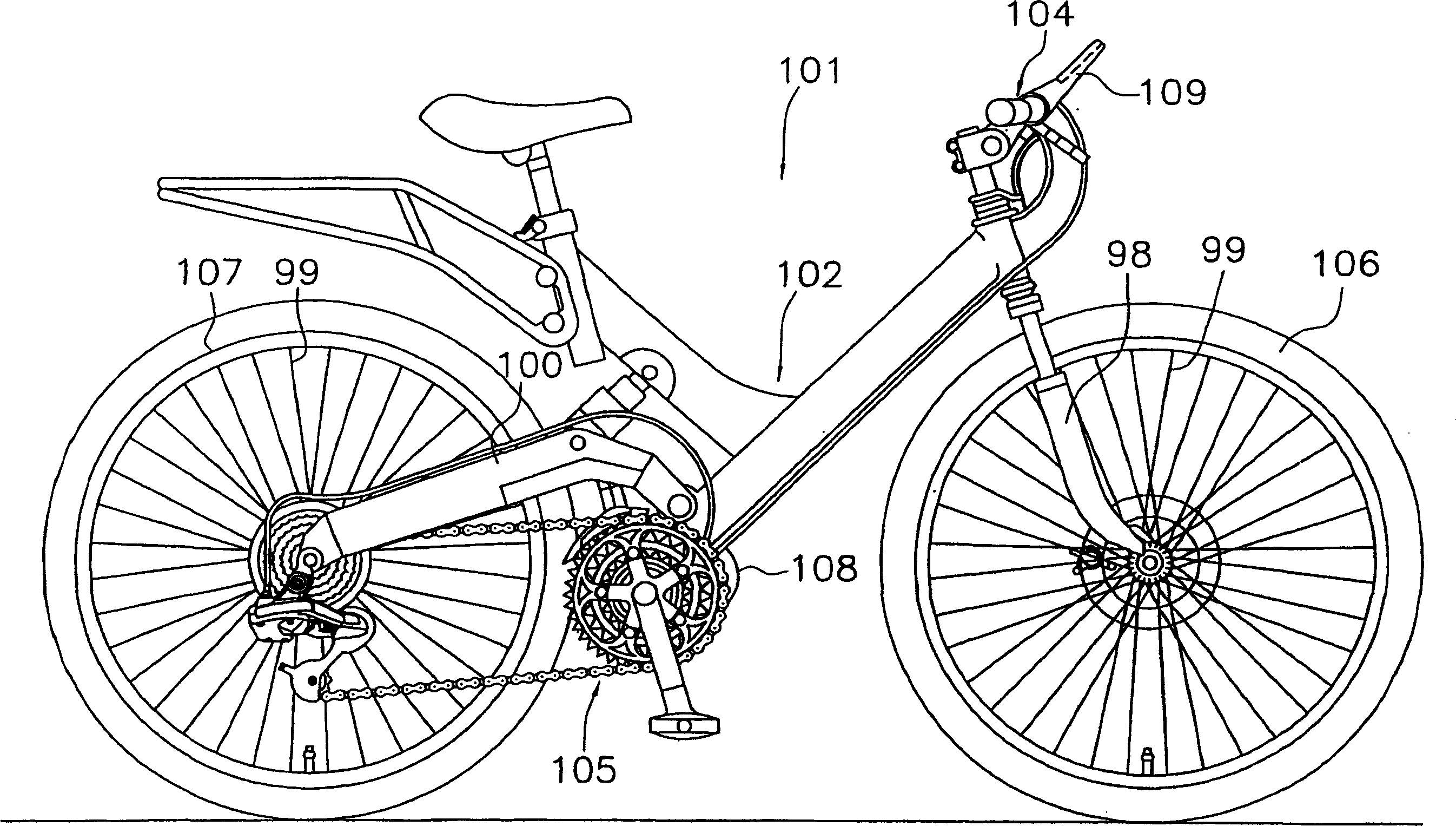
[0035] exist figure 1Among them, the bicycle 101 that adopts the first embodiment of the present invention has the front and rear suspension frame 102 that includes the suspension fork 98 at the front and the vibrating arm 100 at the rear, and the handle 104 that is fixed on the suspension fork 98 is connected by a chain, The driving part 105 that pedal and derailleur etc. constitute, is installed on the suspension fork 98 and the vibrating arm 100, has the front wheel of spoke 99 and rear wheel 106,107, controls two derailleurs and the suspension device of front and back. A control device 108,109. The hub dynamo 1 is provided on the rear wheel 107 . The control device 108 is provided in the vicinity of the hanger portion at the center lower portion of the vehicle frame 102 . The control device 109 has a display unit and is attached to the handle 104 . Electric power from the hub dynamo 1 is supplied to the control devices 108 , 109 and through the control devices 108 , 109...
no. 2 Embodiment
[0072] In the aforementioned first embodiment, the hub dynamo having the quick release mechanism 50 was illustrated, but as Figure 11 As shown, the present invention is also applicable to hub dynamos mounted on the rear portion 202a of the vehicle frame 202, typically by nuts 150,151. In addition, in the second embodiment, the brake mounting part 211 is a separate part from the housing body 212 that screw-in the fixing cover member 213, and is pressed into and fixed on the housing body 212, and is centered on the brake drum of the roller brake 155. 155a ground installation.
[0073] exist Figure 11 Among them, the hub shaft 205 of the hub dynamo 201 is a rod-shaped member having external thread portions 205 a to 205 d formed on the outer periphery thereof. The inner fixing assembly 17 of the generator mechanism 9 is fixed on the hub shaft 205 . External thread part 205a and Figure 10 The nut 150 on the right side, the lock nut 215d and the ball pushing member 215b are s...
no. 3 Embodiment
[0078] In the above two embodiments, the hub bodies 6 and 206 are opened on the freewheel 10 mounting side, but as shown in FIG. 12 , the hub body 306 may be opened on the brake mounting portion 311 side.
[0079] In FIG. 12 , the hub shaft 305 of the hub generator 301 has substantially the same shape as the hub shaft 5 . On the hub shaft 305, the inner fixing assembly 17 of the power generating mechanism 9 is fixed.
[0080] The hub body 306 has a shell body 312, which is screwed into and fixed on the shell body 312 Figure 11 Cover member 313 on the left end face. The shell body 312 has a left hub shell 312a and a right hub shell 312b, wherein the left hub shell 312a has a two-stage outer peripheral surface with a hub flange 312c, and the right hub shell 312b has a hub flange 312d. On the left end surface of the left hub shell 312a, a multifunctional opening 312g for fitting the power generating mechanism 9 is formed, and in the opening 312g, an internal thread portion 312...
PUM
 Abstract
Description
Claims
Application Information