Contactless cutting mould for numerical control turret punch press

A CNC turret punching machine, no-contact technology, applied in the field of non-contact cutting molds for CNC turret punching machines, can solve the problems of time-consuming and labor-intensive, obvious bump marks on the edge of sheet punching, affecting efficiency, etc.

Inactive Publication Date: 2012-08-15
JIANGSU JINFANGYUAN CNC MACHINE CO LTD
View PDF9 Cites 8 Cited by
  • Summary
  • Abstract
  • Description
  • Claims
  • Application Information

AI Technical Summary

Problems solved by technology

[0002] As a cold processing machine tool, CNC turret punching machine is mainly used for punching, forming, edge trimming, small bending, tapping and other work of sheet metal. Due to the limitation of mold size, it is necessary to use mold step After the punching is completed, usually the die punches off one piece of the plate each time during nibbling, and after the plate moves a certain distance, the mold punche...

Method used


Image

  • Contactless cutting mould for numerical control turret punch press
  • Contactless cutting mould for numerical control turret punch press
  • Contactless cutting mould for numerical control turret punch press

Examples


Embodiment Construction

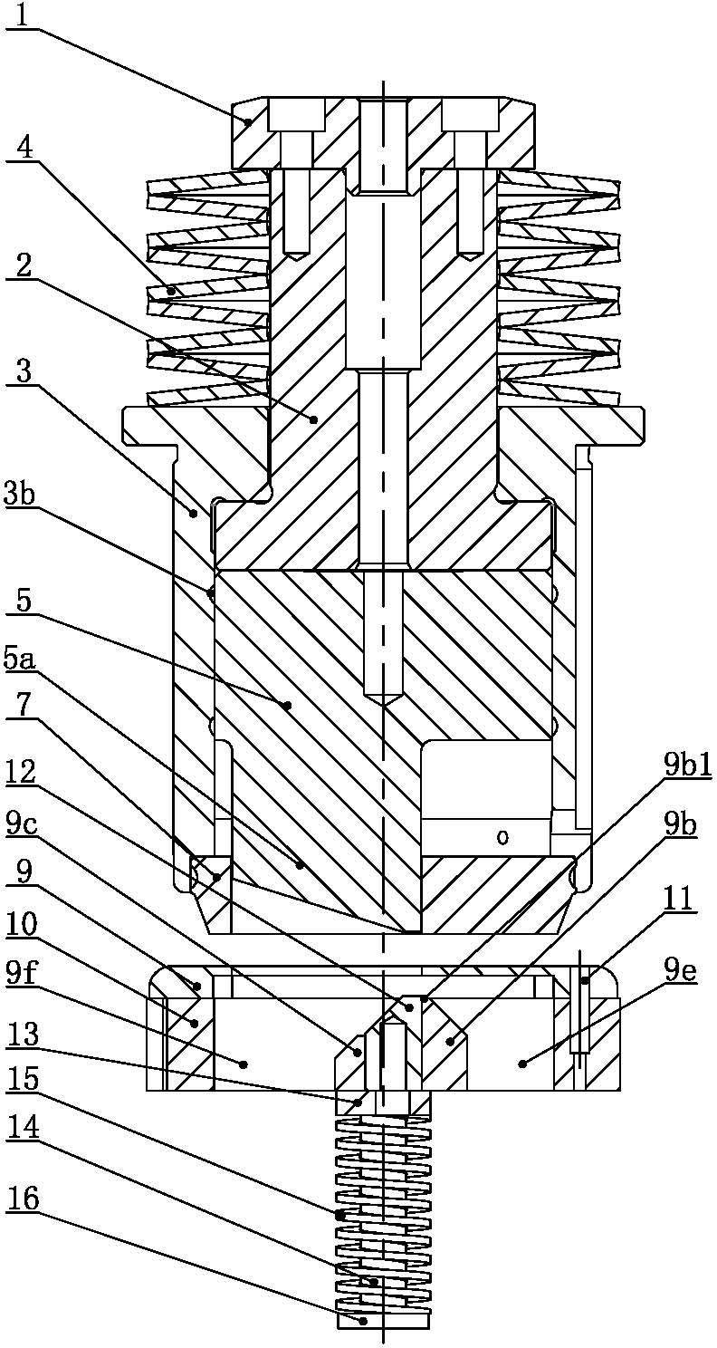
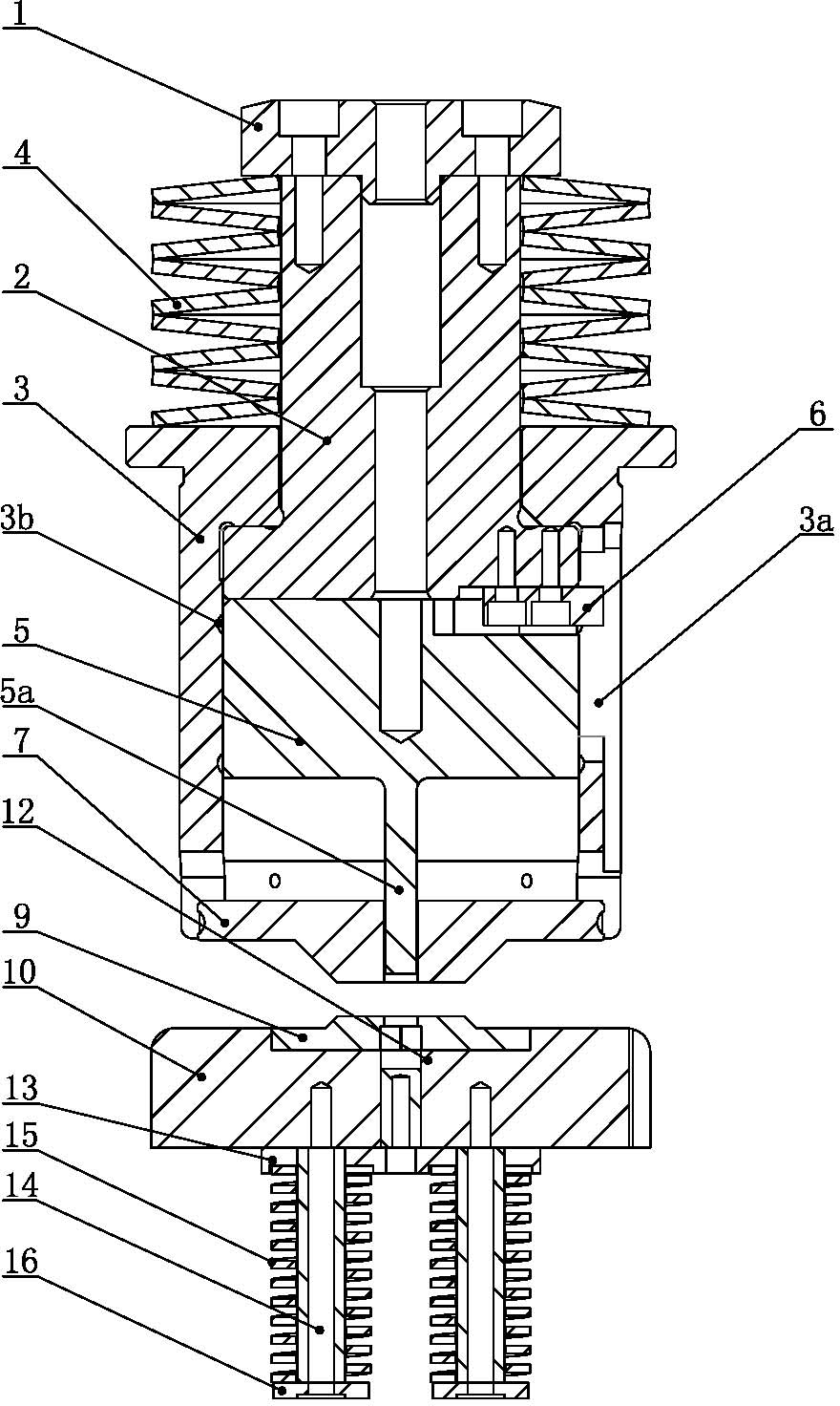
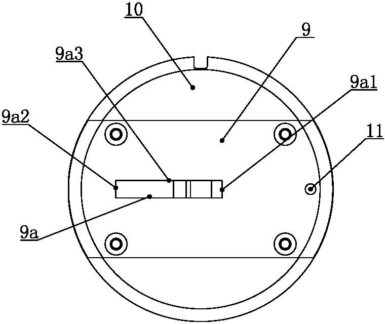
[0025] Such as figure 1 , figure 2 , image 3 and Figure 4 As shown, the non-contact cutting die for the CNC turret punch press of the present invention comprises an upper die assembly and a lower die assembly, and the upper die assembly includes a die nut, an upper die spring, an upper die rod, an upper die core, a guide sleeve and a back die assembly. The material plate and the die rod are in the shape of a stepped cylinder with a small upper part and a larger lower part. The upper die spring is set on the upper part of the upper die rod. The die nut is fixed on the upper end of the upper die rod to compress the upper die spring. The lower end of the upper die spring is supported on the guide On the upper end surface of the sleeve, the inner hole of the guide sleeve is provided with an inner hole step and is supported on the shoulder of the upper die rod through the inner hole step. The lower part of the upper die rod is fixedly connected with the upper die core, and the...


PUM


Abstract

The invention relates to a contactless cutting mould for a numerical control turret punch press. An upper mould spring is sleeved at the upper part of an upper mould rod and a mould nut is fixed at the upper end of the upper mould rod to tightly press the upper mould spring; the lower end of the upper mould spring is supported on an upper end face of a guide sleeve and an inner hole of the guide sleeve is provided with a step to be supported on a rod shoulder of the upper mould rod; the lower part of the upper mould rod is fixedly connected with an upper mould core, and the lower part of the upper mould rod and the upper mould core are located in the inner hole of the guide sleeve and can move up and down along the inner hole of the guide sleeve; the lower part of the upper mould core is provided with a rectangular cutting edge; the lower end face of the cutting edge of the upper mould core is gradually inclined upwards along an opposite direction of a feeding direction of a sheet material; the lower end face of the guide sleeve is fixed with a material returning plate and the material returning plate is provided with a rectangular hole which is matched with the cutting edge of the upper mould core in size; the upper end face of a lower mould is provided with a rectangular edge opening which is matched with the cutting edge of the upper mould core and a material ejection rod guide groove which is composed of a front backer and a back backer is arranged below the rectangular edge opening; and the material ejection rod guide groove is internally provided with a material ejection rod. When the mould is used for pushing and cutting off the sheet material, pushing and cutting convex points are not generated and the edge of the sheet material is smooth and beautiful.

Description

technical field [0001] The invention relates to a numerically controlled turret punch, in particular to a non-contact cutting die for a numerically controlled turret punch. Background technique [0002] As a cold processing machine tool, CNC turret punching machine is mainly used for punching, forming, edge trimming, small bending, tapping and other work of sheet metal. Due to the limitation of mold size, it is necessary to use mold step After the punching is completed, usually the die punches off one piece of the plate each time during nibbling, and after the plate moves a certain distance, the mold punches out one piece again, but at the joint of the two punchings, there will be obvious bumps on the edge of the punching of the plate trace. For the process with high processing requirements, it is necessary to use a file or a grinder to remove the punching bumps at the knife joint, which is time-consuming and laborious, affecting efficiency, and the presence of punching bum...

Claims


Application Information

Patent Timeline
IPC IPC(8): B21D28/14
Inventor 吴宏祥王其柱
Owner JIANGSU JINFANGYUAN CNC MACHINE CO LTD
Why Eureka
Try Eureka