LED (light-emitting diode) backlight drive circuit, liquid crystal display device and drive method

A technology of backlight drive circuit and LED light bar, which is applied in the direction of electrical components, static indicators, instruments, etc., can solve the problems of poor adjustment accuracy, achieve the effects of improving efficiency, wide adjustment range, and improving comparison accuracy

Active Publication Date: 2012-08-15
CHANGSHA HKC OPTOELECTRONICS CO LTD
View PDF5 Cites 43 Cited by
  • Summary
  • Abstract
  • Description
  • Claims
  • Application Information

AI Technical Summary

Problems solved by technology

[0002] like figure 1 As shown, the existing LCD backlight is composed of many strings of LED light strips, and there will be a voltage difference between the strings, so when designing the backlight, it is necessary to find the string with the largest voltage difference to meet the requirements. Optical brightness and error requirements. To find the LED light bar with the largest voltage difference, the current practice is to nest a multi-channel comparator inside the IC. The multi-channel comparator includes a reference terminal and multiple comparison terminals. The reference terminal is connected to To a fixed reference voltage, the comparison terminals are respectively connected to the output terminals of the LED light strips. The multi-channel comparator compares the LED light strips two by two, and finds the string with the largest voltage difference and feeds it back to the power supply terminal. However, this technical solution Poor adjustment accuracy

Method used


Image

  • LED (light-emitting diode) backlight drive circuit, liquid crystal display device and drive method
  • LED (light-emitting diode) backlight drive circuit, liquid crystal display device and drive method
  • LED (light-emitting diode) backlight drive circuit, liquid crystal display device and drive method

Examples


Embodiment 1

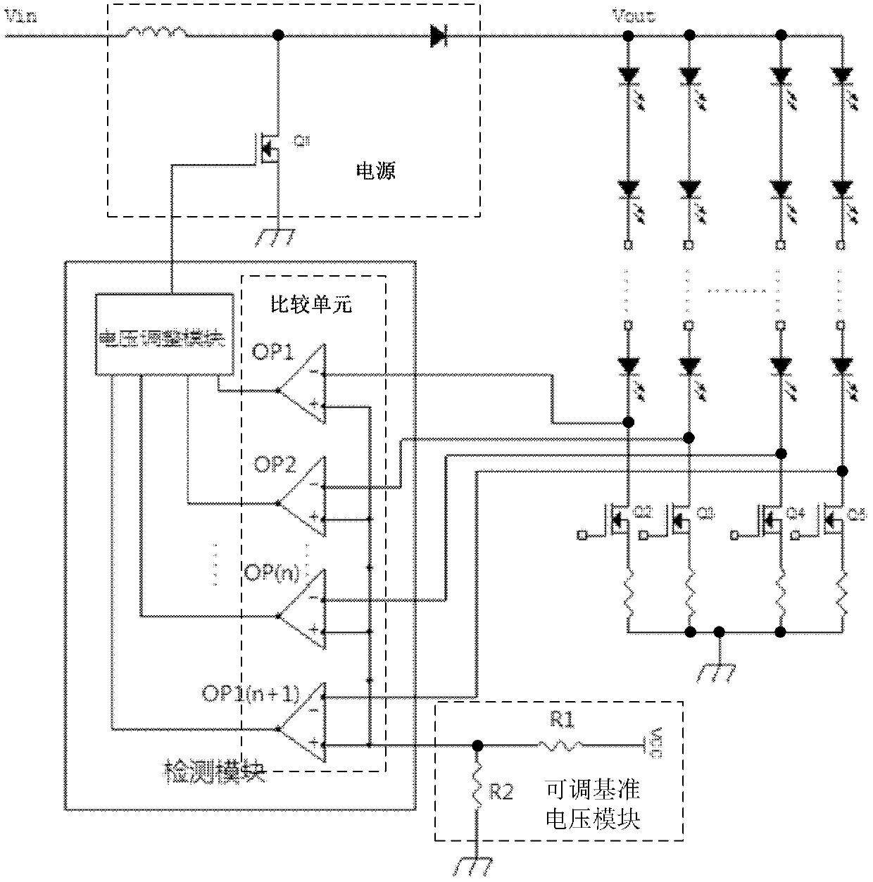
[0026] Such as figure 2 As shown, the comparison unit includes a plurality of comparators OP1~OP(n+1), the comparison terminal of each comparator is correspondingly coupled to the output terminal of an LED light bar, and its reference terminals are connected to each other; the adjustable reference voltage module includes a series One end of the first resistor R1 is connected to a fixed reference voltage, and the other end is connected to the second resistor R2; one end of the second resistor R2 is connected to the first resistor R1, and the other end is grounded; each comparison The reference end of the resistor is coupled between the first resistor R1 and the second resistor R2. The comparison unit is divided into multiple comparators, and each comparator only collects the voltage of one LED light bar, the charge burden is small, the heat generation is reduced, and the heat of the comparison unit is distributed to multiple separate comparators, which can improve the heat dis...

Embodiment 2

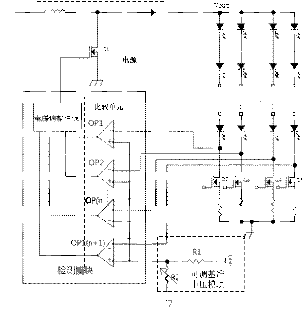
[0030] Such as image 3 As shown, the comparison unit includes a plurality of comparators OP1~OP(n+1), the comparison terminal of each comparator is correspondingly coupled to the output terminal of an LED light bar, and its reference terminals are connected to each other; the adjustable reference voltage module includes a series The first resistor R1 and the second resistor R2, one end of the first resistor R1 is connected to a fixed reference voltage, and the other end is connected to the second resistor R2; the second resistor R2 is an adjustable resistor, one end of which is connected to the first resistor R1, and the other end is connected to the second resistor R2 One terminal is grounded; the reference terminal of each comparator is coupled between the first resistor R1 and the second resistor R2. The comparison unit is divided into multiple comparators, and each comparator only collects the voltage of one LED light bar, the charge burden is small, the heat generation i...

Embodiment 3

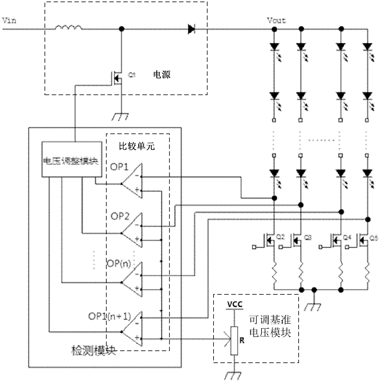
[0034] Such as Figure 4 As shown, the comparison unit includes a plurality of comparators OP1~OP(n+1), the comparison terminal of each comparator is correspondingly coupled to the output terminal of an LED light bar, and its reference terminals are connected to each other; the adjustable reference voltage module includes an adjustable An adjustable resistor R, one end of the adjustable resistor R is connected to a fixed reference voltage, and the other end is grounded; the reference end of each comparator is coupled to the output end of the adjustable resistor R. The comparison unit is divided into multiple comparators, and each comparator only collects the voltage of one LED light bar, the charge burden is small, the heat generation is reduced, and the heat of the comparison unit is distributed to multiple separate comparators, which can improve the heat dissipation efficiency. It is beneficial to detect the heat dissipation of the module.

[0035] The detection module also...


PUM


Abstract

The invention discloses an LED (light-emitting diode) backlight drive circuit, a liquid crystal display device and a drive method. The LED backlight drive circuit comprises a plurality of LED lamp bars arranged in parallel and a detection module, wherein a comparing unit is arranged in the detection module, the comparing end of the comparing unit is respectively coupled to the output ends of the LED lamp bars, and the reference end of the comparing unit is coupled with an adjustable reference voltage module. Due to the adoption of the comparing unit, and the reference end of the comparing unit is coupled with the adjustable reference voltage module, different reference voltage values can be selected according to the voltages of the output ends of the LED lamp bars of different liquid crystal displays, the difference of the voltages of the output ends of the LED lamp bars and the reference voltage is controlled within a reasonable range, the comparing accuracy can be effectively improved, then the maximal difference is fed back to the power source end of a drive, and the output of the power source is regulated.

Description

technical field [0001] The invention relates to the field of liquid crystal display, and more specifically relates to an LED backlight driving circuit, a liquid crystal display device and a driving method. Background technique [0002] Such as figure 1 As shown, the existing LCD backlight is composed of many strings of LED light strips, and there will be a voltage difference between the strings, so when designing the backlight, it is necessary to find the string with the largest voltage difference to meet the requirements. Optical brightness and error requirements. To find the LED light bar with the largest voltage difference, the current practice is to nest a multi-channel comparator inside the IC. The multi-channel comparator includes a reference terminal and multiple comparison terminals. The reference terminal is connected to To a fixed reference voltage, the comparison terminals are respectively connected to the output terminals of the LED light strips. The multi-chann...

Claims


Application Information

Patent Timeline
Patent Type & Authority Applications(China)
IPC IPC(8): G09G3/34G09G3/36
CPCH05B45/35H05B45/40H05B45/46
Inventor 黎飞高新明杨翔
Owner CHANGSHA HKC OPTOELECTRONICS CO LTD
Why Eureka
Try Eureka