Control method of converter interconnection system and control circuit of converter

A technology for controlling circuits and interconnection systems, applied in the direction of electrical components, output power conversion devices, etc., can solve the problems of increasing wiring, increasing system complexity, and inconvenient use for users

Active Publication Date: 2019-09-10
MORNSUN GUANGZHOU SCI & TECH
View PDF6 Cites 0 Cited by
  • Summary
  • Abstract
  • Description
  • Claims
  • Application Information

AI Technical Summary

Problems solved by technology

In the case where the input is connected in series and the output is connected in parallel, an independent closed-loop converter module should be used to achieve voltage equalization at the input end, which generally increases the wiring, increases the complexity of the system, and is not convenient for users to use.

Method used


Image

  • Control method of converter interconnection system and control circuit of converter
  • Control method of converter interconnection system and control circuit of converter
  • Control method of converter interconnection system and control circuit of converter

Examples


Embodiment Construction

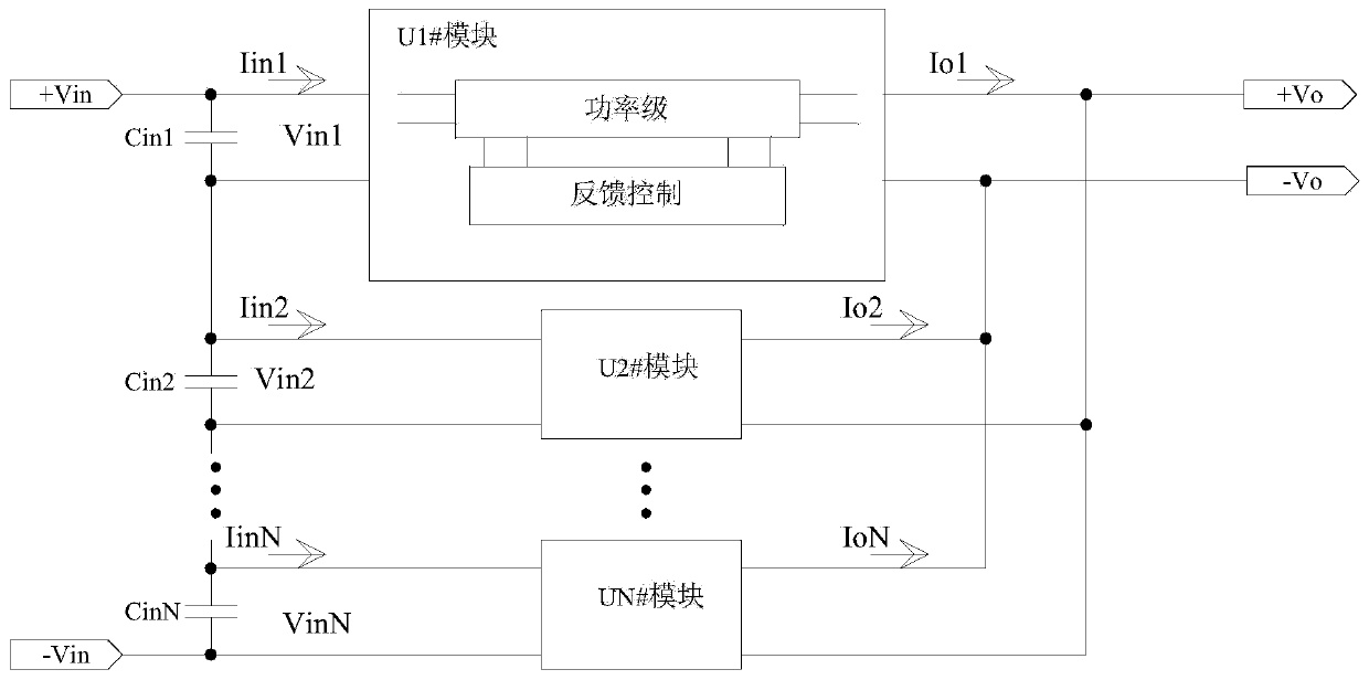
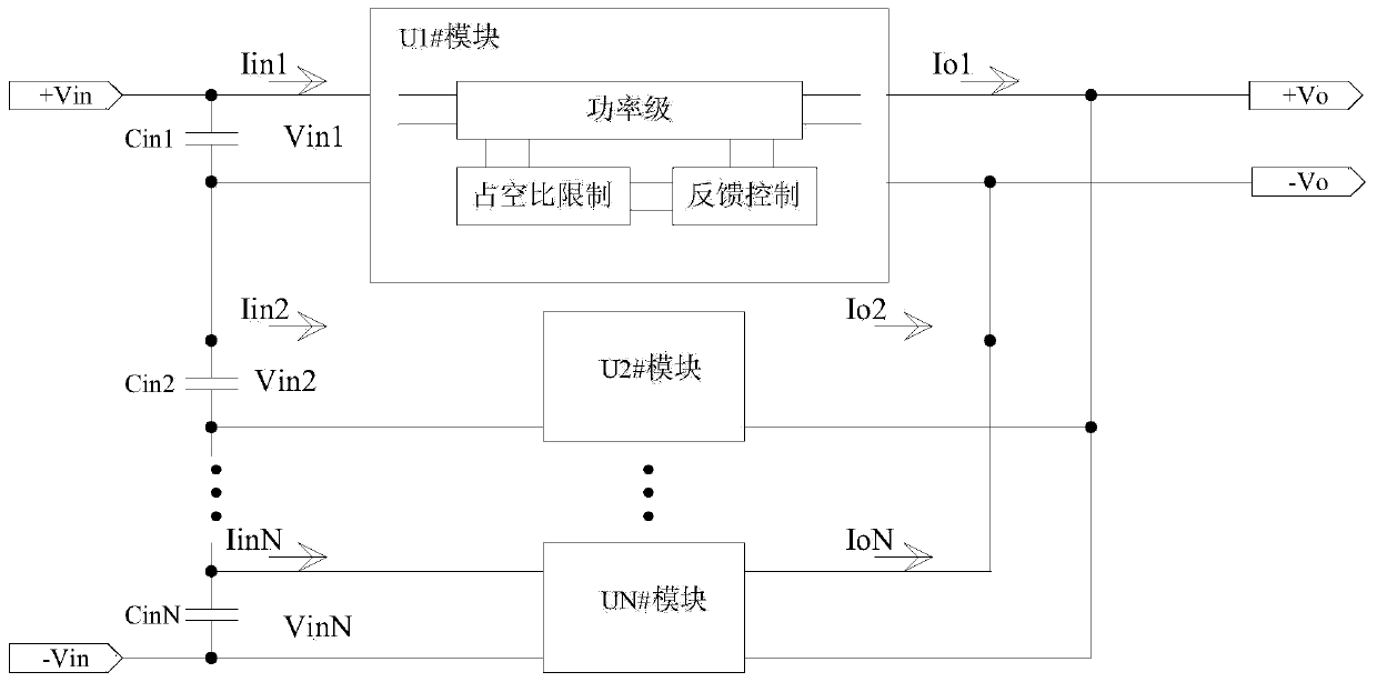
[0022] In the case of converter module input in series and output in parallel, the traditional control method is to take measures to equalize the input voltage of the converter module, so as to ensure that the converter module will not be overvoltage or overloaded. In the present invention, it is not Take measures to equalize the input voltage, and ensure the reliable operation of the converter module by limiting the minimum and maximum duty cycle. like figure 2 As shown, a converter interconnection system introduces a duty cycle limiting circuit in each converter module to ensure reliable operation of the converter. Wherein, the internal structure of each converter module is the same as that of the U1 converter module.

[0023] In the present invention, by limiting the duty cycle of the switching tubes in each converter module, in the case of the input of the converter modules being connected in series and outputting in parallel, although the input voltages of each converte...


PUM


Abstract

The invention relates to a switching converter module, in particular to a control method for a converter interconnection system composed of a plurality of converters connected in series and in parallel and a feedback control circuit for a single converter. Among them, the present invention provides a control method for a converter interconnection system, which is used to realize the system control of multiple converters connected in series and output in parallel, by limiting the maximum duty cycle and minimum duty cycle of the main switching tube in a single converter , so that the maximum input power of the converter module is limited, so as to realize the output voltage regulation of the converter interconnection system through the independent closed-loop voltage regulation of a single converter.

Description

technical field [0001] The invention relates to a switching converter module, in particular to a control method for a converter interconnection system composed of a plurality of converters connected in series and in parallel and a feedback control circuit for a single converter. Background technique [0002] In the case of high input voltage, the input of the switching converter module needs to be used in series; when the power required by the load is greater than the power of a single converter module, the output of the converter module needs to be used in parallel. The input voltage of the power system after the combination of N converter modules is N times the highest input voltage of a single converter module, and the output power is also N times that of a single converter module. Therefore, for occasions with high input voltage and high output power, it is necessary to use the converter modules in series for input and parallel for output. [0003] In the case of input ...

Claims


Application Information

Patent Timeline
Patent Type & Authority Patents(China)
IPC IPC(8): H02M1/00
CPCH02M1/00H02M1/0003H02M1/007H02M1/0074
Inventor 王志燊郭启利
Owner MORNSUN GUANGZHOU SCI & TECH
Why Eureka
Try Eureka