Frequency modulation (FM) antenna implementation device and mobile terminal
An antenna and FM signal technology, which is applied in the field of mobile communications, can solve the problem of FM antenna occupying a large space and achieve miniaturization design, improve user experience, and overcome the effect of occupying a large space
- Summary
- Abstract
- Description
- Claims
- Application Information
AI Technical Summary
Problems solved by technology
Method used
Image
Examples
Embodiment 1
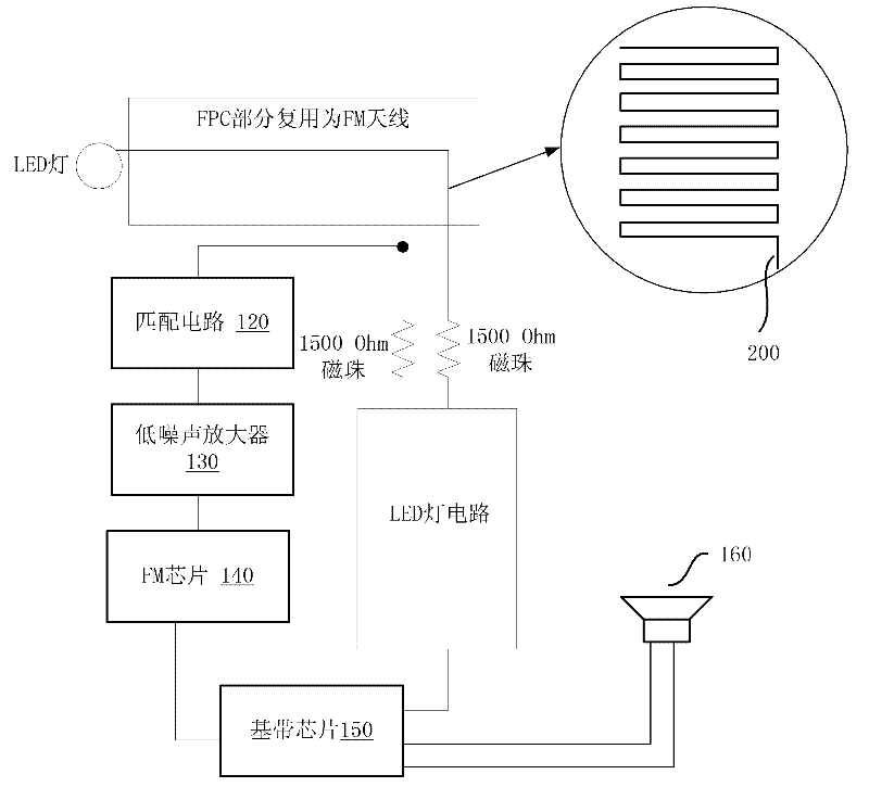
[0031] In this embodiment, a flexible printed circuit board (FPC) is used as an FM antenna built into the mobile terminal. The FPC may be an FPC with electrical characteristics in the mobile terminal, that is, an FPC as a part of a circuit, and it is not excluded that an FPC is separately designed as an FM antenna.
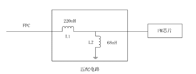
[0032] figure 1 It is a schematic structural diagram of the built-in FM antenna device of this embodiment. In this embodiment, the FPC between the LED lamp circuit and the LED lamp is multiplexed as an FM antenna. In other embodiments, the FPC used for other electrical functions may also be multiplexed as an FM antenna. Such as figure 1 As shown, one end of the metal trace on the circuit board (FPC) connected to the ground and / or power supply is connected to the isolation device and the matching circuit 120, the isolation device and the matching circuit are connected in parallel, and the other end of the isolation device is grounded and / or power supply; FPC ( S...
Embodiment 2
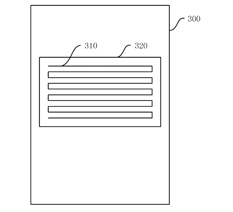
[0042] In this embodiment, a PCB (printed circuit board) is used instead of the FPC in Embodiment 1 to realize FM reception. image 3 It is a schematic diagram of the position of the PCB in the mobile terminal 300 using the PCB as the built-in FM antenna. What is described in this schematic diagram is a mobile terminal 300 with an FM external speaker function. The FM antenna 310 of its PCB (printed circuit board) material is located in a region 320 in the middle of the mobile terminal, and is connected to the main board of the mobile terminal through the spring pins. . The FM antenna 310 made of PCB is disposed in the middle of the mobile terminal 300 , and there is a large space available for receiving FM signals. In addition, there is a main board of the mobile terminal 300 under the FM antenna 310, and the electrical connection between the main board and the main board is relatively easy. In fact, it is also possible for the FM antenna 310 to be arranged on the upper and ...
Embodiment 3
[0046] In this embodiment, the FM antenna made of FPC is also used as the FM antenna built into the mobile terminal. In this embodiment, the FM antenna made of FPC is built into the mobile terminal and preferably follows a setting principle, which can be set by Figure 4a and 4b It can be visualized, specifically:
[0047] Once the length of the FM antenna area made of FPC material is greater than the width, the routing direction of the serpentine line is along the length direction, and the width needs to be considered only when the length is guaranteed to be the longest. It is a design principle to make the FM antenna as long as possible rather than wide. The design of FM antennas with irregular patterns should also follow this principle. Figure 4a and Figure 4b The schematic diagrams of two FM antenna layouts are respectively shown. In the two layouts, the long side of the FM antenna area is the length direction of the FM.
[0048] This principle can also be followed ...
PUM
 Abstract
Description
Claims
Application Information
 - R&D
- Intellectual Property
- Life Sciences
- Materials
- Tech Scout
- Unparalleled Data Quality
- Higher Quality Content
- 60% Fewer Hallucinations
Browse by: Latest US Patents, China's latest patents, Technical Efficacy Thesaurus, Application Domain, Technology Topic, Popular Technical Reports.
© 2025 PatSnap. All rights reserved.Legal|Privacy policy|Modern Slavery Act Transparency Statement|Sitemap|About US| Contact US: help@patsnap.com


